
Service manual


2
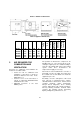
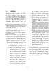
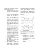
Figure 1: Appliance Dimensions
Table 3: Appliance Dimensions
B' Dia. Venting E' Dia.
Model “I”
“K” “L” W' ‘S’
Water
Connection
Gas
Connection
Outdoor
Condensing
or Sidewall
Standard
Air Inlet
(Optional)
MF2010
6”
68” 34 ⅝”
54 ¾”
33 3/8”
3” 1 ½”
12”
12” 14” 12”
MF2500
6”
72”
34
⅝”
79” 58” 3” 2” 14”
14” 16” 14”
MF3000
6”
72”
34
⅝”
79” 58” 3” 2” 14”
14” 16” 14”
MF3500
6”
72”
34
⅝”
103” 81 ¾”
4” 2 ½”
16”
16” 18” 16”
MF4000
6”
72”
34
⅝”
103” 81 ¾”
4” 2 ½”
16”
16” 18” 16”
3 AIR REQUIRED FOR
COMBUSTION AND
VENTILATION
Provisions for combustion and ventilation air
must be in accordance with:
• Section 5.3. Air for combustion and
Ventilation, of the latest or current as
amended National Fuel Gas Code,
ANSI Z223.1, or;
• Sections 7.2, 7.3 or 7.4 of the latest or
current as amended CAN/CGA B149
Installation Codes, and;
• Applicable provisions of the local
building codes.
The operation of exhaust fans, compressors, air
handling units etc. can rob air from the room,
creating a negative pressure condition leading to
reversal of the natural draft action of the venting
system. Under these circumstances an
engineered air supply is necessary.
If the heater is to be installed near a corrosive or
potentially corrosive air supply, the heater must
be isolated from it and outside air should be
supplied as per code.
Potentially corrosive atmospheres will result
from exposure to permanent wave solution,
chlorinated waxes and cleaners, chlorine, water
softening chemicals, carbon tetrachloride,
halogen based refrigerants, Freon cleaning
solvents, hydrochloric acid, cements and glues,
masonry washing materials, antistatic fabric
softeners, dry cleaning solvents, degreasing
liquids, printing inks, paint removers, etc.