
Service manual


3
4 ELECTRICAL WIRING
All electrical wiring to the appliance must be
electrically bonded to ground in accordance with
the requirements of the authority having
jurisdiction or, in the absence of such
requirements, with the National Electrical Code,
ANSI/NFPA 70 or the Canadian Electrical Code
Part I, CSA C22.1, Electrical Code.
Provide disconnecting means of sufficient rating
within sight of the appliance. These heaters
require an 115V 60 Hz supply. A 15-amp
breaker is sufficient for appliances with input up
to 3,000 MBTUH. For appliances with input over
3,000 MBTUH, use a 20-amp breaker. The
pump requires a separate power supply.
Electrical connections must be made so that the
circulator will operate before the gas valve can
open. At no time may the control system allow
the burner to fire without water flowing in the
system.
Use minimum 18-gauge conductor for 24-volt
field wiring to appliance. Splicing of wires is not
recommended. Use sealed tight conduit suitable
for outdoor use for outdoor installations. Use
terminal strip provided inside control panel for
low water cut-off and remote controller. Refer to
wiring diagram provided with appliance.
5 NORMAL GAS SUPPLY
This appliance is intended to operate at inlet gas
pressures not exceeding 1/4 PSI (7“W.C.) when
firing with natural gas. If higher pressures are
present, consult the gas company for correction.
The appliance and its individual gas shut-off
valve must be disconnected from the supply
piping, when pressure testing the gas supply
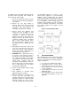
piping at pressures above ½ PSI. Provide a trap
(drip leg) as close to the heater as possible.
Install a ground joint union and manual shut-off
valve in the gas line near the heater to allow
easy removal of the gas control assembly. The
gas pressure at the appliance’s inlet must be set
in accordance with Table 4.
Table 4: Gas Pressure Limits at Inlet to Appliance
PROPANE
NATURAL GAS
Min. Running (inches W.C.)
10 4
Max.
Lockup
(inches W.C.)
11
14
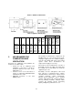
The gas supply line must be of adequate size to
prevent undue pressure drop and must never be
smaller than the size of the connection on the
heater. Table 5 lists recommendation for gas
pipe sizes. Before operating the appliance, the
complete gas train and all connections must be
tested using non-corrosive soap solution.
Table 5: Gas pipe size for distance from natural
gas meter or propane second stage regulator
Input
Btu/Hr
0-100 FT*
NAT. L.P.
2,000,000 2 ½” 2”
2,500,000 3” 2 ½”
3,000,000 3” 2 ½”
3,500,000 3” 2 ½”
4,000,000 4” 2 ½”
Input
Btu/Hr
100-200 FT*
NAT. L.P.
2,000,000 3” 2 ½”
2,500,000 3” 2 ½”
3,000,000 4” 3”
3,500,000 4” 3”
4,000,000 4” 3”
Input
Btu/Hr
200-300 FT*
NAT. L.P.
2,000,000 3” 2 ½”
2,500,000 4” 3”
3,000,000 4” 3”
3,500,000 4” 3”
4,000,000 4” 3”