©2012 Phason Inc. All rights reserved.
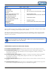
Limited warranty Software Phason Inc. (Phason) warrants for a period of 90 days from the date of purchase that the software product will execute its programming instructions when properly installed on the personal computer or workstation indicated on this package. Phason does not warrant that the operation of the software will be uninterrupted or error free.
Service and technical support Phason will be happy to answer all technical questions that will help you use your OMNI-Select system.
Styles The following styles are used in the manual. All buttons and tabs are bolded. For example, click OK to save the changes. All keyboard keys are UPPERCASE. For example, press the UP or DOWN key on your keyboard. All filenames and directories are in a monospace font. For example, the reports directory in Windows Vista is C:\Users\\Documents \phason\OmniSelect\Reports\. Hint/tip This is a hint or tip.
iv
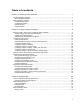
Table of contents Chapter 1: Introducing Select Ventilation ...................................................................................... 1 Introducing Select Ventilation ................................................................................................................... 1 Select Ventilation features .................................................................................................................... 1 Select Ventilation windows ........................................
Appendices ................................................................................................................................... 81 Appendix A: Worksheets ......................................................................................................................... 81 Master settings worksheet .................................................................................................................. 82 Variable stage settings worksheet ........................................
Chapter 1: Introducing Select Ventilation Introducing Select Ventilation Select Ventilation windows Introducing Select Ventilation Select Ventilation has the flexibility to satisfy almost every barn type and ventilation strategy. The system fits the site instead of forcing the site to fit the system. You can configure Select Ventilation for either natural or forced ventilation strategies: tunnel, sidewall forced, curtain, or chimney ventilation systems.
Features PBx-10 PBx-11 Notes Variable AC stages 2 2 Heat or cool Variable DC stages 2 2* Heat or cool General-purpose relays 6 9 Heat, cool, duty cycle, curtain, timed event, or actuator Alarm relay Automatic 4-probe temperature averaging Requires additional probes Functions available at the control Group set point, test, override, and actuator calibration Power-failure memory protection Wireless adapter compatibility Phason Wireless Adapter Four-character display and status LEDs
Select Ventilation windows Temperature charts display ambient and set point temperatures for a Power Block. Temperature charts are useful for tracking down problems in a zone, analyzing the effects of different ventilation strategies, and monitoring conditions. Temperature charts display as line charts. For more information about Select Ventilation viewers, charts, and reports, read Chapter 3: Analyzing data on page 63.
C B A D A E This area lists your devices and their status. To see a list of communication and system messages for a specific device, click on that device. B This button opens a window that displays all messages for all devices. C This button opens a window that displays version information. D This button opens the OMNI-Select login window, which is where you enter your username and password to access other areas of the system.
Select Ventilation windows Configuration window The Configuration window is where you configure the structure of your site, as well as Select Ventilation options you configure seldom or only once at the beginning. A B C A This button displays the configuration window. B This button displays the configuration for Select Ventilation. C This is a list of Power Blocks in each building at your site and where you select the device you want to configure.
Settings window The Settings window is where you program Power Blocks and equipment settings. A B C A This button displays the Settings window. B This button displays the settings for Select Ventilation. C This is a list of Power Blocks in each building at your site and where you select the device you want to set up. For more information about the Settings window and setting up Power Blocks, read What you need to know before programming Power Blocks on page 21.
Select Ventilation windows Reports window A C B A This button displays the reports window. B This button displays the available Select Ventilation reports. C This is where you select the report and details. For more information about the Reports window, read Creating reports on page 74.
8
Chapter 2: Configuring Select Ventilation What you need to know before configuring Select Ventilation Configuring Power Blocks What you need to know before programming Power Blocks Programming Power Block settings What you need to know before configuring Select Ventilation The Configuration window is where you configure the structure of your site, as well as Power Block options you configure seldom or only once at the beginning.
C This is a list of Power Blocks in each building at your site and where you select the device you want to configure. D This is the name, address, and type of the selected Power Block. E The top two buttons open the Power Block description window, which is where you add a new Power Block or edit the selected Power Block. The bottom button removes the selected Power Block from your system. F This button opens the Power Block configuration window, which is where you configure the selected Power Block.
What you need to know before configuring Select Ventilation To add a Power Block 1. In the main window, click Configuration, and then Ventilation. 2. Click Add Power Block. The Power Block description window displays. 3. Beside Name, type a descriptive name for the Power Block. 4. Beside Address, type the address of the Power Block, exactly as it appears on the product. For information about where to find the address, see the installation guide for your Power Block. 5.
3. Make the changes. Beside Name, type a descriptive name (maximum 15 characters) for the device. Beside Address, type the address of the device, exactly as it appears on the product. For information about where to find the address, see the Power Block installation guide. Beside Type, select the model of the Power Block. Beside Building, select the building in which the device is located.
Configuring Power Blocks Activating and deactivating Power Blocks When you add a Power Block, its status is automatically set to active. When a Power Block is active, you can configure and set up the Power Block, as well as view and print charts and reports for it. When a Power Block is inactive, you do not send or receive data from it. You can view and print charts and reports for it using existing data. To activate or deactivate a Power Block 1.
Features PBx-10 PBx-11 Notes Variable AC stages 2 2 Heat or cool Variable DC stages 2 2* Heat or cool General-purpose relays 6 9 Heat, cool, duty cycle, curtain, timed event, or actuator Alarm relay Automatic 4-probe temperature averaging Requires additional probes Functions available at the control Group set point, test, override, and actuator calibration Power-failure memory protection Wireless adapter compatibility Phason model PWA-MULTI Four-character display and status LEDs
Configuring Power Blocks The Power Block configuration window is where you configure Power Blocks. A B C D A This button opens the Power Block cloning window, which is where you can copy configuration and settings from another Power Block. B These buttons open the Relay configuration window, which is where you select the function and enter a description for the relays.
You cannot cancel or undo a Power Block cloning. To clone a Power Block 1. In the main window, click Configuration and then Ventilation. 2. Below Your Power Blocks, select the Power Block you want to configure and then click Configure Power Block. The Power Block configuration window displays. 3. Click Clone Power Block. The Power Block cloning window displays. 4. Select the Power Block you want to copy. 5. Click OK to copy the configuration and return to the Power Block configuration window.
Configuring Power Blocks If you are installing a Phason Rain Sensor to a PBx-10, you can only install three additional probes. This is because the sensor plugs into the probe 2 terminal. Actuator deicing Actuator deicing opens the actuator by 10% when it has not moved for 2 hours. After the actuator moves the 10%, it moves back to its proper position. By default, actuator icing is not enabled.
Configuring variable stages Variable stages control equipment that operates with gradually increasing voltage, such as variable speed fans, or gradually decreasing voltage, such as heat mats. For more information about how variable stages work, read Programming variable stages on page 46.
Configuring Power Blocks To configure variable stages 1. In the main window, click Configuration, and then Ventilation. 2. Below Your Power Blocks, select the Power Block you want to configure and then click Configure Power Block. The Power Block configuration window displays. 3. Click Edit VAR 1 (or VAR 2 to 4 if you are configuring one of the other variable stages). The Variable stage configuration window displays. 4. Configure the variable stage. Beside Name, type a descriptive name for the stage.
Configuring relays for actuators Each actuator you connect requires one relay for opening and one for closing. Power Blocks PBx-10, PB-1, and PB-3 can control one actuator. Power Blocks PBx-11, PB-2, PB-4, and PB-5 can control two actuators. Configuring relays for actuators means: Selecting the relays Entering a descriptive name A good description helps you identify the stage more easily.
Configuring Power Blocks 3. Click Edit relay 4 for actuator 1, or Edit relay 6 for actuator 2. The Relay configuration window displays. 4. Select Actuator 1. 5. Beside Name, type a descriptive name for the actuator. 6. If you are using tunnel mode, select Closed during tunnel mode. 7. If the actuator needs to close when it is raining, select Closed when raining. This option is available only if you have a Phason Rain Sensor connected. 8.
Configuring relays for curtain control Curtains are usually controlled by equipment called curtain machines, which are sometimes referred to as winches. Curtains are opened to let in more air, or closed to let in less air. The theory behind curtain control is more air cools the building. Each curtain machine requires two relays: one for opening the curtain, one for closing the curtain.
Configuring Power Blocks The Relay configuration window displays. 4. Select Curtain open. The window updates and asks you to select the close relay. If there is only one relay available, an Information window displays. Read the information and then click OK. Follow the instructions from the window. 5. Beside Unused relays, select a relay to use for closing the curtain. 6. Beside Name, type a descriptive name for the curtain. 7. If you are using tunnel mode, select Closed during tunnel mode. 8.
Configuring relays for heating, cooling, and duty cycle Relays configured for heating can control equipment such as electric or gas heaters that can be either on or off. The relays switch on when the temperature drops below the set point and off when it rises above. Relays configured for cooling can control single-speed fans, misters, or other cooling equipment that can be either on or off. The relays switch on when the temperature rises above the set point and off when it drops below.
Configuring Power Blocks The Relay configuration window displays. 4. Select one of the options: Heating, Cooling, Duty cycle healing, or Duty cycle cooling. The window updates. 5. Beside Name, type a descriptive name for the relay. 6. If you are using tunnel mode, select Off during tunnel mode. This function is available only for cooling and duty cycle cooling. 7. Click OK to save the changes and return to the Power Block configuration window. 8.
Configuring relays for timed events Relays configured for timed events can be used to switch lights on and off or control equipment that must operate at specific times each day, regardless of temperature. An event is a switch from on to off, or from off to on. For example, switching the yard lights on at 8:00 PM and off at 7:00 AM is two events. Configuring relays for timed events means selecting the timed event function and entering a descriptive name.
Configuring Power Blocks The Relay configuration window displays. 4. Select Timed event. The window updates. 5. Beside Name, type a descriptive name for the relay. 6. Click OK to save the changes and return to the Power Block configuration window. 7. If required, repeat steps 3 to 8 for other relays you want to configure for timed events. 8.
Configuring relays for disconnecting DC variable stages This section is for PBx Power Blocks only. Many variable frequency drives require a disconnect relay to start and stop operation. When configured as a disconnect relay, the relay switches off when the DC stage it is assigned to is off. Configuring relays for disconnecting DC variable stages means selecting the function and entering a descriptive name. Use the Installation and configuration worksheets when configuring Power Blocks.
What you need to know before programming Power Blocks 4. Select Disconnect for one of the DC variable stages. The window updates. 5. Beside Name, type a descriptive name for the relay. 6. Click OK to save the changes and return to the Power Block configuration window. 7.
Program Power Block settings before programming equipment settings. The Settings window is where you program Power Blocks. A F G H B I C J D E A This button displays the Settings window. B This button displays the settings for Select Ventilation. C This is a list of Power Blocks in each building at your site and where you select the Power Block you want to program. D This is information about the selected Power Block. E This is basic status information for the selected Power Block.
Programming Power Block settings H This button opens the Power Block Status viewer, which is where you can view a more-complete overview of the Power Block, including the status of the variable and relay stages. For more information, read Viewing the status of a Power Block on page 63. I This is the setbacks area. The indicators show which setbacks are enabled. The button opens the Temperature setbacks window, which is where you program and enable temperature setbacks.
Empty room mode Empty room mode is a power saving feature that allows you to put a Power Block in an idle state. Because empty room mode has its own settings, you do not have to change your normal, operational settings. When you place a Power Block in empty room mode, it uses the empty room settings. When you return the Power Block to normal mode, it returns to using the normal settings. In empty room mode, there is no active cooling, no tunnel mode, no ventilation curves, and no temperature setbacks.
Programming Power Block settings 3. Click OK to save the changes and return to the Settings window. Programming the master set point The master set point is the desired or target temperature for the room or zone. Make sure you program the master set point before programming the equipment set points. If you adjust the master set point, Select Ventilation adjusts the set points for each variable and relay stage relative to the master set point.
To program the master set point 1. In the main window, click Settings, and then Ventilation. 2. Below Your Power Blocks, select the Power Block you want to program and then click Edit settings. The Ventilation settings window displays. 3. Below Master set point, click and drag the slider up or down. To adjust the temperature by 0.1degree increments, click the slider and then press UP or DOWN on your keyboard. 4. Click OK to save the changes and return to the Settings window.
Programming Power Block settings The Tunnel mode settings window displays. 4. Click and drag the slider up or down. To adjust by smaller, 0.1-degree increments, click the slider and then press UP or DOWN on your keyboard. 5. Click Close to return to the Ventilation settings window. 6. Click OK to save the changes and return to the Settings window. Programming ventilation curves As animals grow, their temperature and ventilation requirements change.
If you are using a master set point curve, you cannot adjust the master set point slider in the main Settings window. You must adjust the curve. Minimum ventilation curves In hog production, minimum ventilation is very important for controlling humidity and getting rid of gases (methane, carbon dioxide, and others). Insufficient ventilation can cause high humidity, high gas levels, and stagnant air. As animals grow older, they require more fresh air, but produce more humidity and gases.
Programming Power Block settings The Ventilation growth curves window is where you program ventilation curves. C A D B E A F This button opens the Growth Curve cloning window, which is where you can copy the curves from another Power Block B This is where you enable or disable curves. When enabled, there is a checkmark in the box beside the curve. The text color corresponds to the color on the chart. The information on the right is the setting for the current day.
Use smoothing to "draw" a straight line between two points. Click Smooth line. Click the first point; in other words, the starting point you want to adjust. Click the second point, the last point you want to adjust. Select Ventilation adjusts all the points between the two selected. First point First point Second point Second point The Power Block must be in normal operation mode to program ventilation curves.
Programming Power Block settings To program curves 1. In the main window, click Settings, and then Ventilation. 2. Below Your Power Blocks, select the Power Block you want to program and then click Edit curves. The Ventilation growth curves window displays. 3. Make the changes to the curve. For more information, read Tips for working with curves on page 37. To enable or disable a curve, below Enabled curves, select or deselect the curve you want.
Power save setback The power save setback lowers the set points for heating equipment by a number of degrees. Each relay or variable configured as heating will have its set point lowered. Using power save is similar to setting your home furnace thermostat a few degrees lower at night so that the furnace switches on at a lower temperature. The difference between the DIF and power save setbacks is that DIF adjusts the master set point, affecting all equipment.
Programming Power Block settings The Temperature setbacks window is where you program the DIF and power save setbacks. A C B D A This is a chart of the baseline set point and setbacks during the day. When you change the setbacks, the chart adjusts automatically. B This is where you enable or disable setbacks. When enabled, there is a checkmark in the box. C This is the setback amount. To change the value, type a number in the box or click Up or Down. D These are the start and stop times.
To program the temperature setback 1. In the main window, click Settings, and then Ventilation. 2. Below Your Power Blocks, select the Power Block you want to program and then click Edit setbacks. The Temperature setbacks window displays. 3. Adjust the DIF settings. To enable or disable the setback, select DIF enabled. There is a checkmark in the box when it is enabled. To change the setback amount, beside Setback, type a number in the box or click Up or Down.
Programming Power Block settings Temperature alarms and alarm biasing Select Ventilation gives you the ability to set low and high temperature alarms. There is a low temperature alarm condition when low alarm is enabled and the temperature is lower than the low set point There is a high temperature alarm condition when high alarm is enabled and the temperature is higher than the high set point.
Select Ventilation adds 5° to the outdoor temperature to create the biased high alarm, up to a maximum of 85 °F. At approximately 6 AM, biasing starts. At approximately 1:30 PM, there is an alarm condition as the ambient temperature exceeds the biased high alarm. Alarm biasing for PB-1 to PB-6 Power Blocks For PB-1 to PB-6 Power Blocks, you set the bias offset.
Programming equipment settings To program temperature alarms 1. In the main window, click Settings, and then Ventilation. 2. Below Your Power Blocks, select the Power Block you want to program and then click Edit settings. The Ventilation settings window displays. 3. Adjust the alarm settings. To enable or disable an alarm, select or deselect Enabled below the alarm you want to change. To adjust an alarm temperature, click and drag its slider up or down. To adjust the temperature by 0.
Programming variable stages Before programming variable stages, make sure you have them properly configured. For more information, read Configuring variable stages on page 18. How variable cooling stages work When the temperature is below the idle range, the fan is off. When the temperature reaches the idle range, the fan runs at the idle speed. The fan continues to run at the idle speed until the temperature rises to the set point.
Programming equipment settings If you need to connect more cooling elements than you have relays available and you have an unused variable stage, you can use it as an ON/OFF stage (for 115/230 VAC-powered equipment only). Set the idle speed to 100% and idle range to the temperature at which you want the stage to switch on/off. You no longer have variable speed or power; you have either full on or full off, the same as a cooling relay.
The Ventilation settings window is where you program the variable stage settings. The following example is for cooling stages. The window for a heating stage is similar. B A C A This button displays the variable stage settings. B This is where you select the variable stage you want to program. C These are the settings for the selected variable stage. The diagram corresponds to the settings. The blue area (or orange for a heat stage) represents when the equipment will be on.
Programming equipment settings Use the Variable stage settings worksheet on page 83 when programming variable stages. If a minimum ventilation curve is enabled, you cannot manually adjust the idle speed for that variable stage. For more information, read Programming ventilation curves on page 35. To program variable stages 1. In the main window, click Settings, and then Ventilation. 2. Below Your Power Blocks, select the Power Block you want to program and then click Edit settings.
Programming actuators means setting the temperature set points, differential, and position for each stage of the actuator. For each actuator, you need to program: Minimum set point temperature Minimum position Set point temperature, differential temperature, and position for stages 1 to 4 How actuators work When the temperature is below the minimum set point, the inlet/actuator is closed. When the temperature rises to the minimum set point, the actuator moves to the minimum position.
Programming equipment settings Position Stage 4 differential Stage 4 set point Stage 3 differential Temperature Stage 3 set point Stage 2 differential Stage 2 set point Stage 1 differential Stage 1 set point Stage 4 position Stage 3 position Stage 2 position Stage 1 position Stage 0 position (minimum position) Stage 0 set point (minimum set point) The Ventilation settings window is where you program actuator settings. B C A D A These buttons display the actuator settings.
C This is where you select the actuator stage you want to program. D These are the settings for the selected actuator and stage. The diagram corresponds to the settings. The blue line represents the actuator settings. The red line represents the ambient temperature. To adjust a setting, click and drag its slider up or down. To adjust a setting by 0.1-degree or 1 percent increments, click the slider and then press UP or DOWN on your keyboard. To adjust a setting by 1.
Programming equipment settings Programming relays for curtain control Curtains control the temperature by adjusting airflow into the facility. Before setting up the curtains, make sure you have properly configured the relays. For more information, read Configuring relays for curtain control on page 22. Programming curtain control relays means programming the following settings.
Time (duration) Open idle (02:00 mm:ss) After the curtain opens for the open run duration, it holds its position for the open idle duration. Temperature Open run (00:30 mm:ss) If the temperature rises above the idle band, the curtain opens for the open run duration. Set point (80°F) Idle band (+/– 1°F) When the temperature is within the idle band, the curtain remains in its current position.
Programming equipment settings A This button displays the curtain settings. B This is where you select the curtain you want program. C These are the set point and idle band settings for the selected curtain. To adjust a setting, click and drag its slider up or down. To adjust a setting by 0.1-degree or 1 percent increments, click the slider and then press UP or DOWN on your keyboard. To adjust a setting by 1.0-degree or 10 percent increments, click the slider and then press PGUP or PGDOWN.
5. Adjust the settings. To adjust the set point or idle band, click and drag its slider up or down. To adjust by 0.1degree increments, click the slider and then press UP or DOWN on your keyboard. To adjust a run or idle duration, click and drag its minute or second number up or down. You can also click the number and then press UP or DOWN on your keyboard. 6. Repeat steps 4 and 5 for each curtain you want to program. 7. Click OK to save the changes and return to the Settings window.
Programming equipment settings Notes about duty cycles Duty cycles always start with the ON duration. When Power Blocks restart after a power failure, duty cycles restart with the ON duration. If the duty cycles resetting could cause a problem at your site, timed events are another option to consider. For more information, read Programming timed events on page 59. The minimum ON or OFF duration is 5 seconds (0:00:05 hours:minutes:seconds).
C This is the set point for the selected relay. To adjust the set point, click and drag its slider up or down. To adjust the set point by 0.1-degree or 1 percent increments, click the slider and then press UP or DOWN on your keyboard. To adjust the set point by 1.0-degree or 10 percent increments, click the slider and then press PGUP or PGDOWN. D These are the duty cycle settings. Duty cycle settings display only if the duty cycle is enabled.
Programming equipment settings 5. Adjust the settings. To adjust the set point, click and drag the slider up or down. To adjust by 0.1-degree increments, click the slider and then press UP or DOWN on your keyboard. To adjust an on or off duration, click and drag its hour, minute, or second number up or down. You can also click the number and then press UP or DOWN on your keyboard. 6. Repeat steps 4 and 5 for each relay you want to program. 7.
A These are the timed event relays for the selected Power Block. B These are the timed events (ON and OFF times) for the selected relay. C This is a graph of timed events for the selected relay. The green sections represent when the relay is on; red sections represent when the relay is off. D This button opens the Timed events setup window, which is where you add and remove timed events for the selected relay. E This is where you add a timed event.
Programming equipment settings 5. Program the timed events. To set an event time, click and drag the number for hour or minute up or down. You can also click the number and then press UP or DOWN on your keyboard. To add the event to the list, click Add as…. To remove an event, select the event you want to remove and then click Remove event. 6. Repeat steps 3 to 5 for each event you want to program. 7. Click OK to save the changes and return to the Timed event settings window. 8.
62
Chapter 3: Analyzing data Tools for analyzing ventilation performance Select Ventilation reports Select Ventilation charts Tools for analyzing ventilation performance Select Ventilation has three main tools for analyzing data. Power Block status viewer (below) Reports (on page 65) Charts (on page 78) Viewing the status of a Power Block The Power Block status viewer displays the status of the Power Block’s variable and relay stages.
To view the status of a Power Block from the Settings window 1. In the main window, click Settings, and then Ventilation. 2. Below Your Power Blocks, select the Power Block you want to view and then click Status viewer. The Power Block status viewer displays. 3. Click Close to return to the Settings window. To view the status of a Power Block from the Reports window 1. In the main window, click Reports, and then Ventilation. 2. Below Viewer, select Status viewer. 3.
Select Ventilation reports Select Ventilation reports One of the great advantages of Select Ventilation is the detailed reports that are available. All reports are available in preview/PDF format. The Ventilation Temperature Report is also available in CSV format. Preview/PDF These reports display using OMNI-Select's built-in Report Preview window. From there, you can print or save reports as a PDF (portable document format).
Ventilation Temperature Report Ventilation Temperature Reports provide detailed temperature history. In addition to selecting the Power Blocks you want in the report, you select a sampling interval and type. Sampling interval Sampling interval is how often there is an entry in the report. You can select a sampling interval of between 10 minutes and 24 hours. In the following example, the sampling interval is 10 minutes. 9:10 9:20 9:30 68.0°F 69.5°F 70.
Select Ventilation reports Ventilation Temperature Reports are available in preview/PDF and CSV formats.
Ventilation Status Report The Ventilation Status Report is a combination of charts, tables, and diagrams that provide an "information snapshot" for each selected Power Block. Status reports are helpful for analyzing problems in rooms or zones. Ventilation Status Reports are available in preview/PDF format only. The following example shows sections from several different Power Blocks so that you can get a better idea of what is available.
Select Ventilation reports Growth curves, in chart format Variable stage cooling status and settings Variable stage heating status and settings 69
Actuator status and settings Curtain settings Relay configuration and settings, sorted by relay number Timed events, sorted by relay and time 70
Select Ventilation reports Ventilation Settings History Report The Ventilation Settings History Report is a combination of tables and diagrams that provide an overview of the settings for the selected Power Block and time. Ventilation Settings History Reports are available in preview/PDF format only. The following example shows sections from different Power Blocks so that you can get a better idea of what is available.
Actuator settings Curtain settings Relay configuration and settings 72
Select Ventilation reports PBx Relay Runtime Report The PBx Relay Runtime Report lists the duration, in hours:minutes:seconds, that each variable stage and relay was on during each day. You select the Power Block(s) and date range. The PBx Relay Runtime Report is available in preview/PDF format only.
Creating reports A E B C F D A This button displays the Reports window. B This button displays the available Select Ventilation reports, viewer, and chart. C This is where you select what you want to view or create. D If required, this is where you select the dates, format, and sampling information. For more information, read Formats, dates, and other information on page 75. E This is a list of Power Blocks in each building at your site and where you select the Power Block(s) you want.
Select Ventilation reports Formats, dates, and other information The following table shows the formats available, date type, and other information required for the reports, viewer, and chart.
To create Current Status Reports 1. In the main window, click Reports, and then Ventilation. 2. Below Reports, select Current status report. The window updates. 3. Below Your Power Blocks, select one or more of Power Blocks. 4. Click Create report. OMNI-Select displays your report in the Report Preview window. From here, you can print or save your report by clicking the appropriate button. 5. Click Close to return to the Reports window. To create Settings History Reports 1.
Select Ventilation reports 5. Select the settings you want. As you make changes, the preview area updates. To change the Power Block, below Your Power Blocks, select the one you want. To move forward through the settings, click Next change; to move backward, click Previous change. To load the current settings, click Current settings. To load the settings from a specific day, below Date, select the date you want. For more information, read Selecting dates below. 6. Click Create report.
2. Select a start date: To move backward or forward through the months, click or . To select a specific month, click the month on the calendar and then select the month you want. To move forward and backward through the years, double-click the year on the calendar and then select the year you want. 3. Repeat steps 1 and 2 for the end date. Select Ventilation charts Select Ventilation charts historical ambient and set point temperatures for a Power Block.
Select Ventilation charts Viewing charts B C A D E G F A H This is a list of Power Blocks in each building at your site and where you select the Power Block you want to view. B This is the legend for the chart. C This is the chart for the selected Power Block and date range. You can zoom in and scroll along the chart. D This is where you select the date range. E This button refreshes the chart and leaves the zoom level the same. Refresh the chart if you change the date range.
To view charts 1. In the main window, click Reports, and then Ventilation. 2. Below Chart, select Temperature chart. The window updates. 3. Below Dates, select the start and end date for the chart. For more information, read Selecting dates on page 77. 4. Below Your Power Blocks, select the Power Block you want in the chart. 5. Click Show chart. The Temperature chart displays. 6. Make any changes to the chart. To change the Power Block, below Your Power Blocks, select the one you want to view.
Appendices Appendix A: Worksheets Appendix B: Motor curves Appendix C: Glossary Appendix A: Worksheets Appendix A contains worksheets to help you program Select Ventilation. Master settings worksheet (on page 82) Variable stage settings worksheet (on page 83) Actuator settings worksheet (on page 85) Curtain worksheet (on page 87) Heating and cooling elements worksheet (on page 88) Timed events worksheet (on page 89) There is one copy of each worksheet.
Master settings worksheet Enter your Power Block settings in the table below. Use the information in the table to program your master settings in Select Ventilation. Configuration and information Name Address Building Type Master set point Master set point This is the target temperature.
Appendix A: Worksheets Variable stage settings worksheet Variable cooling stages Programming variable cooling stages means programming the following settings. For more information, read Programming variable stages on page 46. Information Name Address Building Type Setting Differential VAR 1 VAR 2 VAR 3 VAR 4 Description The fan is at full speed when the temperature is at or above this value.
Variable heating stages Programming variable heating stages means programming the following settings. For more information, read Programming variable stages on page 46.
Appendix A: Worksheets Actuator settings worksheet Programming actuator relays means programming the following settings. For more information, read Programming relays for actuator control on page 49.
Information Name Address Building Type Setting Actuator jam alarm Minimum set point Minimum position Stage 1 set point Stage 1 differential Stage 1 position Stage 2 set point Stage 2 differential Stage 2 position Stage 3 set point Stage 3 differential Stage 3 position Stage 4 set point Stage 4 differential Stage 4 position ACT 1 Yes ACT 2 No Yes Description No Select Ventilation displays and alarm message when it detects an actuator jam.
Appendix A: Worksheets Curtain worksheet Programming curtain control relays means programming the following settings. For more information, read Programming relays for curtain control on page 53. Information Name Address Building Type Setting Set point Idle band Open run Open idle Close run Close idle Curtain 1 Curtain 2 Curtain 3 Curtain 4 Description When the temperature is at the set point +/– half the idle band, the curtain holds its position.
Heating and cooling elements worksheet There are two types of heating and cooling element setups: standard and duty cycle. Programming a standard element means programming the temperature set point. Programming a duty cycle means programming the temperature set point and the ON and OFF durations. For more information, read Programming heating, cooling, and duty-cycle relays on page 56.
Appendix A: Worksheets Timed events worksheet Timed event relays control equipment such as lights that need to be switched on or off during certain times of the day. Setting up timed events means setting the on and off times. For every on time, there must be an off time. For more information, read Programming timed events on page 59.
Appendix B: Motor curves Motor curves provide a way to proportionally increase or decrease speed, regardless of motor manufacturer. For example, a Multifan motor might require 130 VAC to run at 50% RPM, while a Marathon motor might need 100 VAC to run at 50% RPM. Without a motor curve, the Multifan motor would run at a slower RPM than the Marathon motor at the same settings.
Appendix C: Glossary Manufacturer Choretime (GE) Emerson Exafan Franklin Leeson Magnetek Marathon Multifan Diameter (inches) 18 12 12 10 14 16 18 20 24 10 14 18 24 24 36 12 12 36 12 24 18 20 Model 4E45 4E50 Specifications 1/3 HP, 1140 RPM 1/6 HP, 3400 RPM 1/4 HP, 1700 RPM 1/4 HP, 1700 RPM 1/3 HP, 1700 RPM 1/3 HP, 1700 RPM 0.53 HP, 1700 RPM 0.
actuator set point When the temperature is below the minimum set point, the actuator is closed. When the temperature rises to the minimum set point, the actuator moves to the minimum position. As the temperature rises, the actuator has four stages it moves through until it reaches its maximum open position. This lets you gradually open inlets instead of fully opening them when the temperature rises above a single set point.
Appendix C: Glossary curtain set point Curtain set point is the target temperature for the curtains. When the temperature is between the curtain set point and idle band limits, the curtains hold their position. Set point is one of six curtain settings. For more information, read Programming relays for curtain control on page 53. See also actuator set point and relay set point. different method (DIF) DIF is a mode of temperature setback.
empty room Empty room mode is a power saving feature that allows you to put a Power Block into an ‘idle state’ and adjust all the settings, without having to change your normal, operational settings. Empty room mode has its own master set point, high and low temperature alarms, and high temperature biasing. In empty room mode, OMNI maintains minimum ventilation only; there is no active cooling, no ventilation curves, and no temperature setbacks.
Appendix C: Glossary minimum position Minimum position is the percentage an actuator will be open when the temperature is at the minimum set point. For more information, read Programming relays for actuator control on page 49. minimum set point Minimum set point is the temperature at which an actuator is at its minimum position. When the temperature is below the set point, the actuator closes completely. For more information, read Programming relays for actuator control on page 49.
96
Index A activating Power Blocks .................................. 12 actuator deicing ............................................... 17 actuators configuring ............................................ 20–21 programming .............................................. 49 adding Power Blocks.... 10–12, See also activating E editing Power Blocks.................................. 10–12 empty room mode ...................................... 31–33 equipment settings ...........................................
reports ...................................... See specific report timed events configuring relays .................................. 25–27 programming ......................................... 59–61 Reports window ................................................. 7 tunnel mode ............................................... 34–35 S V sampling .......................................................... 66 variable stages configuring ............................................. 18–19 programming .....
99
2 Terracon Place Winnipeg, Manitoba Canada R2J 4G7 Phone Fax E-mail Web site 204-233-1400 204-233-3252 support@phason.ca www.phason.