
Product Manual
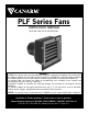


User’s Guide for All PLF Series Models
Congratulations on the purchase of your new High Performance Plastic Fan. This fan is made of materials that ensure
long lasting performance and is designed with features that make it one of the most efficient and easy to use and care
for fans available today.
Your fan comes completely assembled except for the metal turn clips that can be quickly assembled into the pre-drilled
holes around the outside flanges of the fan. All fans are tested for proper operation before leaving the factory. Your fan
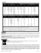
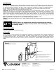
should be installed into a wood frame. See Chart #1 for dimensions.
Rough Inside Opening Frame Dimension
INSTALLATION
PLF36 Models
Remove the fan from the shipping pallet by removing the 6 screws holding the fan to the pallet. A hardware bag is
secured to the motor support arm. The hardware bag contains 8 turn clips, 8 nylon washers, 8 10-24 x 3/4" stainless
steel screws, and 8 nylon insert nuts. This hardware is for the turn clips that hold the shutter assembly in place.
Assemble the 8 turn clips to the pre-drilled holes. There are 3 holes down each side flange and 1 on each of the top
and bottom flanges. For each of the 8 turn clips insert the screw through the hole from the back of the flange, slide on
a nylon washer, then the clip, and thread the nut. Tighten the turn clips with a Phillips screw driver and a 3/8" socket
wrench. (see Figure 1-b).
PLF09 to PLF24 Models
Simply remove the fan from the carton and proceed to next section.
All Fan Models
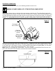
With the shutter removed, slide the fan into the framed opening. Push the fan up against the top of the frame to be sure
the fan slopes downward for drainage to the outside. Secure the 4 corners with lag bolts. Secure the 4 sides being
sure the inside dimensions of the fan are consistent between flanges so that clips and shutters will operate correctly.
(see Figure 1-a) This will also ensure that the orifice, is not deformed which may cause the blade to hit the tunnel of the
fan.
Caution: If using expanding foam to insulate, make sure expansion pressure does not damage the housing.
Chart #1
Inside View of Fan
-BeSure All Similar
Dimensions Are Equal
When Mounting Fan
Mounting
Fan Flange
Turn Clip
Hex Locknut
Machine Screw
Clip Detail
Figure 1-b
Figure 1-a
Nylon Washer
Model H W
PLF09 15.00" 15.00"
Model H W Model H W
PLF12 15.00" 15.00" PLF18 21.25" 21.25"
PLF16 19.25" 19.25" PLF24 27.25" 27.25"
PLF14 17.25" 17.25" PLF20 23.25" 23.25"
PLF36 40.25" 40.25"
PLF48 52.25" 52.25"
M0017 - Rev.5-Rev Date: 22/04/03
Page 2 of5