CANON INC. 30-2, Shimomaruko 3-chome, Ohta-ku, Tokyo 146-8501, Japan U.S.A. CANON U.S.A. INC. For all inquiries concerning this camera, call toll free in the U.S. 1-800-OK-CANON or write to: Customer Relations, Canon U.S.A., Inc. One Canon Plaza, Lake Success, N.Y. 11042-1198 CANADA CANON CANADA INC. HEADQUARTERS 6390 Dixie Road, Mississauga, Ontario L5T 1P7, Canada CANON CANADA INC. MONTREAL BRANCH 5990, Côte-de-Liesse, Montréal Québec H4T 1V7, Canada CANON CANADA INC.
Thank you for purchasing a Canon product. The Canon Speedlite 550EX is a powerful, high-output flash unit featuring ETTL (Evaluative-Through-The-Lens) autoflash control. It can be used as an oncamera Speedlite or as a master or slave unit in a wireless, multi-Speedlite system. When used with Type-A cameras (listed below), the 550EX obtains natural-looking flash pictures by balancing the flash output and existing light.
01. F073-E (3~) 02.4.1 2:07 PM Page 3 Conventions Used in this Booklet The Instructions are divided into separate sections for Type-A and Type-B cameras. If you have a Type-A camera, see pages 10 to 76 and 112 to 125. If you have a Type-B camera, see pages 10 to 22 and 77 to 125. ● The Speedlite operation procedures assume that the Speedlite 550EX has been turned on with its main switch. Before proceeding, turn on the main switch.
01. F073-E (3~) 02.4.1 2:07 PM Page 4 Contents Nomenclature .........................................6 Before You Start For Type-B Cameras For Type-A Cameras Basic Flash Photography 4 Advanced Flash Photography Wireless Flash Photography Basic Flash Photography Advanced Flash Photography Wireless Flash Photography 1. 2. 3. 4. 5. Installing Batteries..........................10 External Power Sources ................12 Attachment to Camera ...................13 Wireless Selector ...............
01. F073-E (3~) 02.4.1 2:07 PM Page 5 • For Type-A cameras, see pages 10 to 76 and 112 to 125. • For Type-B cameras, see pages 10 to 22 and 77 to 125. 6. Pilot Lamp and Test Firing..........17 7. Flash Exposure Confirmation .....18 8. Using the Zoom Button and Wide Panel .................................18 9. Flash Mode.................................21 10. Setting the Film Speed ...............21 11. LCD Panel Illumination ...............21 12. AF-Assist Beam..........................
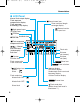
01. F073-E (3~) 02.4.1 2:07 PM Page 6 Nomenclature ● Front Built-in Wide Panel (retracted) (page 20, 42) Flash head and transmitter Sensor Battery compartment cover (page 10) * The battery compartment has a switch to display the distance in feet or meters on the LCD panel.
01. F073-E (3~) 02.4.
01. F073-E (3~) 02.4.
02. F073-E (9~) 02.4.1 2:08 PM Page 9 Before You Start This chapter is for preparing the Speedlite 550EX for actual operation.
02. F073-E (9~) 02.4.1 2:08 PM Page 10 1. Installing Batteries Speedlite 550EX requires one of the following two types of batteries: (1) Size-AA alkaline batteries × 4 (2) Size-AA nickel-hydride batteries × 4 the battery compartment cover 1 Slide as shown by the arrow and flip it up. 1 2 the batteries with the + and – 2 Insert contacts oriented as shown in the battery compartment. 1 10 2 the battery compartment cover 3 Close as shown in the figure.
02. F073-E (9~) 02.4.1 2:08 PM Page 11 Installing Batteries • Use four new batteries of the same type. When replacing batteries, replace all four batteries at one time. • Size-AA lithium batteries can also be used. • Although non-alkaline, manganese batteries may also be used, the number of flashes will be less. • Remove the batteries when the 550EX will not be used for an extended period. • In low temperatures, take two sets of batteries and keep one set warm in a pocket, etc.
02. F073-E (9~) 02.4.1 2:08 PM Page 12 2. External Power Sources Speedlite 550EX can use any of the following two external power sources. For details, refer to the Instructions of the respective external power source. (1) Transistor Pack E Uses Canon Battery Magazine TP (six size-C alkaline batteries) or Ni-Cd Pack TP. (2) Compact Battery Pack CP-E2 Uses six size-AA alkaline or nickel-hydride batteries. Size-AA lithium batteries can also be used.
02. F073-E (9~) 02.4.1 2:08 PM Page 13 3. Attaching the Speedlite to the Camera the locking collar by turning it 1 Loosen as shown by the arrow. the Speedlite’s mounting foot 2 Slip into the camera’s hot shoe until it stops. the locking collar as shown by 3 Turn the arrow and tighten. (The mounting foot’s locking pin will extend into the hot shoe.) • To detach the Speedlite, turn the locking collar in the opposite direction until it stops. (The locking pin retracts into the mounting foot.
02. F073-E (9~) 02.4.1 2:08 PM Page 14 4. Wireless Selector The wireless selector has three settings as shown below. Set to OFF to use the 550EX as a normal, on-camera Speedlite. Set to MASTER to use the 550EX as the master unit in a wireless, multi-Speedlite system. Set to SLAVE to use the 550EX as a slave unit in a wireless, multi-Speedlite system.
02. F073-E (9~) 02.4.1 2:08 PM Page 15 Wireless Selector If the 550EX is to be used as a normal, on-camera Speedlite but the wireless selector has been set to or , the following applies: : If master flash ON has also been set, it will be the same as using the Speedlite at the wireless selector’s OFF setting. If master flash OFF has been set, a picture cannot be taken. : It will be the same as using the Speedlite at the wireless selector’s OFF setting.
02. F073-E (9~) 02.4.1 2:08 PM Page 16 5. Main Switch The main switch has three settings as shown below. Turns off the power. Turns on the power. Turns on the power and enables the SE mode. • The SE (Save Energy) mode turns off the Speedlite automatically after a period of non-use as indicated in the following table. Wireless Selector Setting OFF MASTER 90 sec. SLAVE 60 min. • When the wireless selector is set to or and the SE mode takes effect, the LCD panel display turns off.
02. F073-E (9~) 02.4.1 2:08 PM Page 17 6. Pilot Lamp and Test Firing 1 Set the Speedlite’s main switch to . • The flash will start charging. When the flash is ready, the pilot lamp lights. ● Red pilot lamp When the flash is fully charged, the pilot lamp lights in red. For normal use, confirm that the pilot lamp is red before taking the picture.
02. F073-E (9~) 02.4.1 2:08 PM Page 18 7. Flash Exposure Confirmation When a correct flash exposure has been obtained, the flash exposure confirmation lamp on the back of the Speedlite lights in yellow-green for 3 sec. If the flash exposure confirmation lamp does not light after the flash fires, the picture may have been underexposed. Move closer to the subject and try again. 8.
02. F073-E (9~) 02.4.1 2:08 PM Page 19 Using the Zoom Button and Wide Panel ● Automatic Flash Head Zooming 1 Turn on the camera. 2 Turn on the Speedlite. • If is displayed, press the < button until turns off. > the camera’s shutter button 3 Press halfway. The current lens focal length will appear on the Speedlite’s LCD panel. ● Manual Flash Head Zooming Press the < > button. and will be displayed. Keep pressing the < > button until the desired zoom setting (focal length) appears.
02. F073-E (9~) 02.4.1 2:08 PM Page 20 Using the Zoom Button and Wide Panel ● Using the Wide Panel PU SH Pull out the built-in wide panel and flip it down to cover the flash head. The flash head’s zoom setting will be set to 17mm automatically. • Using the wide panel disables the < > button. • Use the wide panel with flash head at the normal or 7° downward tilt position. • If the built-in wide panel is used and the flash head is turned or tilted for bounce flash, the flash result may look uneven.
02. F073-E (9~) 02.4.1 2:08 PM Page 21 9. Flash Mode The following flash modes can be set with the < > button: E-TTL (or TTL) autoflash, manual flash, and stroboscopic flash. Pressing the < > button changes the flash mode in the following loop: / 10. Setting the Film Speed The film speed is set automatically according to the film speed set with the camera. 11. LCD Panel Illumination Press the < > button to illuminate the LCD panel for 12 sec. To turn off the illumination, press the < > button again.
02. F073-E (9~) 02.4.1 2:08 PM Page 22 12. AF-Assist Beam In low-light or low-contrast situations, the Speedlite emits the AF-assist beam automatically to assist autofocusing. The AF-assist beam is compatible with the AF of all EOS cameras. The AF-assist beam is effective with 28mm and longer lenses. Its effective range in darkness is indicated in the table below. See page 123 for details on when the AF-assist beam is emitted. Position Effective Range Center Approx. 0.6 - 10 m / 2 - 33 ft.
03. F073-E (23~) 02.4.1 2:09 PM Page 23 For Type-A Cameras Basic Flash Photography When the Speedlite 550EX is attached to a Type-A camera such as the EOS3, you can take flash pictures with E-TTL autoflash as easily as normal autoexposure (AE) pictures. As with evaluative metering, the E-TTL autoflash system uses a multi-zone sensor. A preflash is fired for evaluative flash metering and the reading is stored in memory.
03. F073-E (23~) 02.4.1 2:09 PM Page 24 1. Using Flash in Full Auto Mode Set the camera’s picture-taking mode to P (Program AE) or (Full Auto). Flash photography will then be as easy as normal AE photography. The camera sets the aperture and shutter speed automatically to suit a wide variety of lighting conditions including outdoor fill flash. The E-TTL autoflash system sets the flash exposure automatically. the camera’s picture-taking mode 1 Set to P. 2 Set the.
03. F073-E (23~) 02.4.1 2:09 PM Page 25 Using Flash in Full Auto Mode the flash fires, check that the 6 After flash exposure confirmation lamp lights. When a correct flash exposure has been obtained, the flash exposure confirmation lamp lights for about 3 sec. If the lamp does not light, the flash may have been insufficient, resulting in underexposure. In such a case, check that the pilot lamp is red, then move closer to the subject and take the picture again.
03. F073-E (23~) 02.4.1 2:09 PM Page 26 2. Using Flash in Other Camera Modes Flash photography is also automatic in the other picture-taking modes. In the Av (aperture-priority AE), Tv (shutter speed-priority AE), and M modes, the E-TTL autoflash system sets the flash exposure automatically. The camera sets the necessary shutter speed (in the Av mode), aperture (in the Tv mode), or flash output (in the M mode). Flash photography is as easy as normal AE picture-taking.
03. F073-E (23~) 02.4.1 2:09 PM Page 27 Using Flash in Other Camera Modes (1) Av: Aperture-Priority AE and E-TTL Autoflash This mode is effective for controlling the depth of field in your flash pictures. You can also obtain a balanced exposure between the subject and background. You set the aperture and the camera sets the shutter speed automatically to obtain a correct exposure for the background. The E-TTL autoflash system obtains the proper exposure based on the aperture you set.
03. F073-E (23~) 02.4.1 2:09 PM Page 28 Using Flash in Other Camera Modes ● Balanced Flash Exposures In low-light situations, the exposure level can be balanced between the subject and background by using a slow sync speed. You can obtain balanced flash exposures automatically by setting the camera’s picture-taking mode to Av. The camera then sets the sync speed automatically to suit the background. Using a tripod is recommended to prevent camera shake. Balanced flash exposure.
03. F073-E (23~) 02.4.1 2:09 PM Page 29 Using Flash in Other Camera Modes (2) Tv: Shutter Speed-Priority AE and E-TTL Autoflash By selecting the shutter speed, you can obtain various effects with flash. You can set the shutter speed from 30 sec. to the top sync speed. The camera then sets the aperture automatically to obtain a correct exposure for the background. The E-TTL autoflash system controls the flash exposure based on the camera-selected aperture.
03. F073-E (23~) 02.4.1 2:09 PM Page 30 Using Flash in Other Camera Modes (3) M: Manual Exposure and E-TTL Autoflash In this mode, you set both the shutter speed and aperture. The E-TTL autoflash system controls the flash exposure based on the the aperture you set. the camera’s picture-taking mode 1 Set to M and set the desired aperture and shutter speed anywhere from 30 sec. to the top sync speed. You can also use buLb. 2 Set the. 550EX’s flash mode to 3 Focus the subject.
04. F073-E (31~) 02.4.1 2:10 PM Page 31 For Type-A Cameras Advanced Flash Photography This section explains advanced flash operations possible with the Speedlite 550EX. It contains the following: 1. High-Speed Sync (FP Flash) (page 32) 2. FE Lock (page 34) 3. Flash Exposure Compensation (page 36) 4. FEB (Flash Exposure Bracketing) (page 38) 5. Bounce Flash (page 40) 6. Close-Distance Flash Photography (page 43) 7. Manual Flash Mode (page 44) 8. Stroboscopic Flash (page 46) 9.
04. F073-E (31~) 02.4.1 2:10 PM Page 32 1. High-Speed Sync (FP Flash) When you set the synchronization mode to high-speed sync (FP flash), the camera can synchronize with the 550EX at all shutter speeds. When highspeed sync has been set, is displayed in the viewfinder. • High-speed sync can be used in the E-TTL and M flash modes. • High-speed sync is especially effective for fill-flash portraits in daylight since you can: (1) Obtain better background blur with a larger aperture.
04. F073-E (31~) 02.4.1 2:10 PM Page 33 High-Speed Sync (FP Flash) that the icon is displayed 5 Check in the viewfinder, then take the picture. With normal flash. With high-speed sync. • With high-speed sync, the Guide No. changes depending on the shutter speed (see page 121). The faster the shutter speed, the shorter the flash range will be. Check the current flash range on the 550EX’s LCD panel.
04. F073-E (31~) 02.4.1 2:10 PM Page 34 2. FE Lock You can use FE (flash exposure) lock with Type-A cameras. This is the flash version of AE lock. With FE lock, you use spot metering to obtain the correct flash exposure reading for a specific part of the subject. • FE lock works with E-TTL and high-speed sync (FP flash). a picture-taking mode with the 1 Select camera. 2 Focus the subject. the viewfinder’s spot metering 3 Aim circle over the part of the subject to be metered.
04. F073-E (31~) 02.4.3 11:23 AM Page 35 FE Lock the flash exposure level in the 6 Check viewfinder, then take the picture. • If the subject is too far away to obtain a correct flash exposure, will blink in the viewfinder. Either move closer to the subject or use a larger aperture (smaller fnumber) and try again. • FE lock cannot be used if the 550EX is set to the M (Manual) flash mode.
04. F073-E (31~) 02.4.1 2:10 PM Page 36 3. Flash Exposure Compensation Flash exposure compensation with the 550EX can be set up to ±3 stops in 1/3-stop increments (or 1/2-stop increments with some cameras). You can also use flash exposure compensation in combination with normal exposure compensation (to control the background’s exposure level) in a flash picture. the < 1 Press select .
04. F073-E (31~) 02.4.1 2:10 PM Page 37 Flash Exposure Compensation that the subject is within the 5 Check flash range displayed on the 550EX’s LCD panel. that the and icons are 6 Check displayed in the viewfinder, then take the picture. • Flash exposure compensation set with the 550EX overrides any flash exposure compensation set with the camera. • If the subject is small and the background is dark, flash exposure compensation may not give the desired result. In such a case, use the manual flash mode.
04. F073-E (31~) 02.4.1 2:10 PM Page 38 4. FEB (Flash Exposure Bracketing) With FEB, you can obtain bracketed flash shots of the subject while the background exposure level remains the same. Three bracketed flash shots can be taken: Correct exposure, decreased exposure, and increased exposure. The three shots can be bracketed up to ±3 stops in 1/3-stop increments (or 1/2-stop increments with some cameras). After all three bracketed flash shots are taken, FEB is canceled automatically.
04. F073-E (31~) 02.4.1 2:10 PM Page 39 FEB (Flash Exposure Bracketing) that the subject is within the 5 Check flash range displayed on the 550EX’s LCD panel. that the icon is displayed in 6 Check the viewfinder, then take the picture. the remaining two bracketed 7 Take shots. (If necessary, repeat steps 4 to 6.) Correct exposure. Decreased exposure by 1 stop. Increased exposure by 1 stop. • The film advances according to the camera’s current film advance mode.
04. F073-E (31~) 02.4.1 2:10 PM Page 40 5. Bounce Flash With direct, frontal flash, harsh shadows are usually created in the background behind the subject. This can be avoided by bouncing the flash off a nearby wall or ceiling. Bounce flash also gives softer lighting effects. turn the flash head, press the 1 To < > button. To tilt the flash head, PUSH press the < > button. Turn and/or tilt the flash head and point it at a wall, ceiling, or other reflective surface.
04. F073-E (31~) 02.4.3 11:23 AM Page 41 Bounce Flash that the icon is displayed in 4 Check the viewfinder, then take the picture. • If the flash exposure confirmation lamp does not light after you take the picture, use a larger aperture (smaller f-number) and try again. With bounce flash. Without bounce flash. Bounce the flash on a plain, white, reflective surface. If a colored surface is used, the picture may have a color cast.
04. F073-E (31~) 02.4.1 2:10 PM Page 42 Bounce Flash ● Creating a Catchlight A catchlight is a reflection of the flash in the subject’s eyes. A catchlight in the eyes makes the subject look more lively. For portraits, you can easily create a catchlight with the 550EX. Tilt the flash head upward all the way by 90˚. Extend the built-in wide panel until it clicks in place as shown in the figure. To take a picture, follow the same procedure in "5. Bounce Flash.
04. F073-E (31~) 02.4.1 2:10 PM Page 43 6. Close-Distance Flash Photography The flash head can be tilted downward by 7°. This position enables the flash to better illuminate the lower part of a subject that is close to the camera. Press the < > button and tilt the flash head downward until it stops. The icon will blink on the LCD panel. PUSH • This flash head position is effective only for subjects 0.5 meter / 1.6 ft to 2 meters / 6.6 ft from the camera.
04. F073-E (31~) 02.4.1 2:10 PM Page 44 7. Manual Flash Mode In the manual flash mode, you can set the flash output from 1/1 (full) to 1/128 power in full-stop increments. • To prevent overheating and deterioration of the flash head, observe the following limits for continuous shooting with flash: (1) At 1/1 or 1/2 output: Max. 15 continuous flash shots. (2) At 1/4 or 1/8 output: Max. 20 continuous flash shots. (3) At 1/16 or 1/32 output: Max. 40 continuous flash shots.
04. F073-E (31~) 02.4.1 2:10 PM Page 45 Manual Flash Mode the < > or < > button to set 4 Press the desired flash output. • Each time the button is pressed, the flash output changes by one stop. the < > button 5 Press again. The manual flash output display will stop blinking and remain displayed. 6 Focus the subject. • When you press the shutter button halfway, focus will be achieved and the aperture and flash range (bar segment) will be displayed on the LCD panel.
04. F073-E (31~) 02.4.1 2:10 PM Page 46 8. Stroboscopic Flash With stroboscopic flash, a rapid series of flashes is fired. It can be used to record multiple images of a moving subject in a single photograph for later study. You can set the firing frequency (the number of flashes per sec. expressed as Hz) from 1 Hz to 199 Hz. The firing frequency can be set in 1-Hz increments from 1 Hz to 20 Hz, in 5-Hz increments from 25 Hz to 50 Hz, and in 10-Hz increments from 60 Hz to 199 Hz.
04. F073-E (31~) 02.4.1 2:10 PM Page 47 Stroboscopic Flash the < > button to 2 Press select the firing frequency, flash count, or flash output display. When selected, the respective item blinks on the LCD panel to indicate that it can be altered. Pressing the < > button changes the blinking item in the following loop: Firing frequency Flash count (Normal display) Flash output the < > or < > button to set 3 Press the desired value for the blinking item.
04. F073-E (31~) 02.4.1 2:10 PM Page 48 Stroboscopic Flash the following formula to calculate 2 Use the required shutter speed. Flash count ÷ Firing frequency = Shutter speed Example: If the flash count is 10 and the firing frequency is 5 Hz, the shutter speed will have to be at least 2 sec. 10 ÷ 5 = 2 • If the flash count display is , the flash will keep firing until the shutter speed ends or until the maximum number of continuous flashes (as indicated in the table on page 122) is fired.
04. F073-E (31~) 02.4.1 2:10 PM Page 49 9. Second-Curtain Synchronization Normally, the flash fires in synchronization with the first shutter curtain when the shutter is fully open. With second-curtain synchronization, the flash fires immediately before the second shutter curtain closes at the end of the exposure.
04. F073-E (31~) 02.4.1 2:10 PM Page 50 10. Modeling Flash When the 550EX is used with the EOS-1D, 1V, 3, D60, D30, ELAN 7/7E, and 30/33, a modeling flash can be fired so you can check the lighting and shadow effects before you take the picture. Set the desired flash photography settings with the camera and 550EX. Press the camera’s depth-of-field preview button. • The aperture will stop down. • The 550EX will fire a series of flashes at 70 Hz for 1 sec.
05. F073-E (51~) 02.4.1 2:12 PM Page 51 For Type-A Cameras Wireless Flash Photography This section covers wireless flash photography with the 550EX. It explains the 550EX’s built-in master and slave flash features. 550EX Wireless Flash Features • A wireless flash system with multiple Speedlite 550EXs can be used as easily as a single, on-camera Speedlite 550EX. • Up to three 550EXs or three groups of 550EXs can be set as slave units for automatic control.
05. F073-E (51~) 02.4.1 2:12 PM Page 52 [1] Wireless System Setup and Testing The wireless flash system can be setup in one of two ways: 1 With a 550EX set as the master unit and one or more 550EXs set as slave units. 2 With Speedlite Transmitter ST-E2 (sold separately) used as the master unit and one or more 550EXs set as slave units. This section describes the procedure for the former. For the latter, refer to the Instructions for Speedlite Transmitter ST-E2. 1.
05. F073-E (51~) 02.4.1 2:12 PM Page 53 2. Setting the 550EX as a Slave Unit Set the wireless selector to on the 550EX to be used as a slave unit. A 550EX set in this way is called a “slave unit.” • The slave unit’s flash head zoom setting is set automatically to . You can change the slave unit’s flash head zoom setting manually with the button.
05. F073-E (51~) 02.4.1 2:12 PM Page 54 3. Setting the Master/Slave Channel To prevent your master unit from firing another photographer’s slave units, four channels are provided to differentiate your slave units from unrelated ones. The master unit and slave unit(s) in the same wireless flash system must be set to the same channel No. set the master unit’s channel No., 1 To press the < > button and select .
05. F073-E (51~) 02.4.1 2:12 PM Page 55 Setting the Master/Slave Channel 5 Press the < > or < > button to set the same channel No. (1, 2, 3, or 4) as the master unit’s. 6 Press the < • The displayed. > button. icon and channel No. will be If the master unit and slave unit(s) are not set to the same channel No., the master unit will be unable to trigger the slave unit’s flash. Make sure the channel No. is the same.
05. F073-E (51~) 02.4.1 2:12 PM Page 56 4. Setting the Slave ID With multiple slave units, a slave ID can be assigned to distinguish a slave unit as being the main flash or fill flash. A flash ratio can thereby be set. Three slave IDs are available: A, B, and C. set a slave unit’s slave ID, press 1 To the < > button and select . • Pressing the < > button changes the selection in the following loop: (Off) the < > or < > button to set 2 Press the slave ID (A, B, or C). 3 Press the < • The displayed.
05. F073-E (51~) 02.4.1 2:12 PM Page 57 5. Master Flash ON/OFF The master unit’s flash firing can be enabled (ON) or disabled (OFF). (1) ( ) : This setting enables the master unit to fire a flash. • This setting is called “Master flash ON.” • This setting automatically sets the master unit’s slave ID to A. (2) ( ) : This setting (Master flash OFF) prevents the master unit from firing a flash. It can still transmit wireless signals to trigger the slave units. the < 1 Press select .
05. F073-E (51~) 02.4.1 2:12 PM Page 58 6. Wireless Flash Range After the master and slave units have been set, position them within the wireless flash range shown below. 15 m / 49.2 ft For indoors For outdoors 10 m / 32.8 ft 80° 8 m / 26.2 ft 12 m / 39.4 ft • Use the mini stand (provided) for the slave unit(s). The mini stand also has a tripod socket. • Use the bounce feature to turn the body of the slave unit so that the sensor is exposed to the master unit.
05. F073-E (51~) 02.4.1 2:12 PM Page 59 Wireless Flash Range that the master unit’s pilot 3 Check lamp is lit and that the slave unit(s) are recharged and ready. • When a slave unit is ready, its AF-assist beam blinks once per second. the master unit’s pilot lamp 4 Press (test firing button) to fire a test flash. • When the wireless transmission works, the slave units fire at 1/64 output in the following slave ID order: A, B, and C.
05. F073-E (60) 02.4.17 3:24 PM Page 60 [2] Wireless E-TTL Autoflash Wireless E-TTL autoflash with multiple Speedlite 550EXs can be used in one of two ways: (1) OFF : All slave units fire at the same flash output. (2) ON : Slave units with different slave IDs (A, B, or C) can be fired at different flash outputs to produce a flash ratio. • A flash ratio can be set only with the EOS-1D, 1V, 3, D60, D30, ELAN 7/7E, and 30/33.
05. F073-E (51~) 02.4.1 2:12 PM Page 61 Wireless E-TTL Autoflash With Flash Ratio OFF for the following icons on the 1 Check master unit’s LCD panel: • • • displayed not displayed displayed sure the master unit’s pilot 2 Make lamp is lit and the slave units are ready. the pilot lamp to test the 3 Press wireless transmission. the subject and take the 4 Focus picture. ● Master Flash OFF + Slave Unit(s) 15 m / 49.2 ft 10 m / 32.8 ft For indoors 12 m / 39.4 ft For outdoors 8 m / 26.
05. F073-E (51~) 02.4.1 2:12 PM Page 62 Wireless E-TTL Autoflash With Flash Ratio OFF for the following icons on the 1 Check master unit’s LCD panel: • • • displayed not displayed displayed sure the master unit’s pilot 2 Make lamp is lit and the slave units are ready. the pilot lamp to test the 3 Press wireless transmission. the subject and take the 4 Focus picture. • The master unit can also be set for bounce flash.
05. F073-E (51~) 02.4.1 2:12 PM Page 63 2. Wireless E-TTL Autoflash With Flash Ratio ON As shown in the figure below, the wireless E-TTL autoflash system described as an example consists of a master unit set to master flash OFF and two slave units. • • • • The slave ID of the slave unit on the camera’s left is A. The slave ID of the slave unit on the camera’s right is B. Master flash OFF is set for the master unit.
05. F073-E (51~) 02.4.1 2:12 PM Page 64 Wireless E-TTL Autoflash With Flash Ratio ON 1 On < the master unit, press the > button and select . • Pressing the < > button changes the selection in the following loop: (Off) 2 Press theON button to select • 3 Press again. ON A:B will blink. the < > button • A:B and (flash ratio bar) will blink. • In the left figure, the flash ratio bar indicates a flash ratio of 1:1. the < > or < 4 Press the A:B flash ratio.
05. F073-E (51~) 02.4.1 2:12 PM Page 65 Wireless E-TTL Autoflash With Flash Ratio ON the < 5 Press register the flash ratio. > button to • The flash ratio bar stops blinking and remains displayed. • To indicate that a flash ratio has been set, A:B will remain displayed on the master unit’s LCD panel. the basic procedure for 6 Follow wireless E-TTL autoflash picturetaking on page 60 and take the picture. • During the setting procedure, A:B and blink for 8 sec. and then remain displayed.
05. F073-E (51~) 02.4.1 2:12 PM Page 66 Wireless E-TTL Autoflash With Flash Ratio ON ● Setting the Flash Ratio for Three Slave Units: A, B and C With three wireless slave units, slave unit A is the main flash, slave unit B is the fill flash, and slave unit C is a supplemental flash. Thus, slave units A and B serve to illuminate the subject for a proper exposure while slave unit C illuminates the background to eliminate shadows.
05. F073-E (51~) 02.4.1 2:12 PM Page 67 Wireless E-TTL Autoflash With Flash Ratio ON The following wireless E-TTL autoflash procedure is for a master unit with three slave units. This procedure sets the A:B flash ratio and the flash exposure compensation amount for slave unit C. • The flash ratio range for A:B is the same as when only two slave units are used. • Flash exposure compensation with slave unit C can be set up to ±3 stops in 1/3 or 1/2-stop increments.
05. F073-E (51~) 02.4.1 2:12 PM Page 68 Wireless E-TTL Autoflash With Flash Ratio ON 4 Press the < • A:B and > button. (flash ratio bar) will blink. the < > or < 5 Press the A:B flash ratio. > button to set • Press the < > button to move the flash ratio bar to the left, or press the < > button to move it to the right on the flash ratio scale. 6 Press the < > button. • The flash ratio bar and remain displayed. 7 Press again. the < A:B:C > button • The for A:B will blink.
05. F073-E (51~) 02.4.1 2:12 PM Page 69 Wireless E-TTL Autoflash With Flash Ratio ON the < 10 Press register the setting. > button to • The flash ratio bar and A:B:C remain displayed. • To change the flash exposure compensation amount, repeat steps 8 to 10. the basic procedure for 11 Follow wireless E-TTL autoflash on page 60 and take the picture. • Even if you have slave units A, B, and C, if only A:B is selected, slave unit C will not fire.
05. F073-E (51~) 02.4.1 2:12 PM Page 70 Wireless E-TTL Autoflash With Flash Ratio ON ● Wireless High-Speed Sync (FP Flash) After setting up the wireless flash system with one or more slave units, you can enable wireless high-speed sync by setting on the master unit. • You need not touch any controls on the slave units. • The procedure for setting wireless high-speed sync is the same as for normal high-speed sync. See page 32.
05. F073-E (51~) 02.4.1 2:12 PM Page 71 [3] Wireless Manual Flash After setting up the wireless flash system, you can manually set the slave unit’s flash output with the master unit. The flash output can be uniform or varied among the slave units. To determine the proper flash exposure, use a hand-held flash meter. 1. Wireless Manual Flash With Uniform Flash Output 1 On < the master unit, press the > button and select M. the < > button and 2 Press select the flash output display.
05. F073-E (51~) 02.4.1 2:12 PM Page 72 2. Wireless Manual Flash With Varied Flash Output You can set a different flash output for each slave unit (A, B, and C) as follows. 1 On < the master unit, press the > button and select M. the < 2 Press select > button and . • Pressing the < > button changes the selection in the following loop: Flash output (Off) to select 3 Press theONorbutton A:B:C • ON A:B or A:B:C will blink. 4 Press the < > button. • A and the flash output display will blink.
05. F073-E (51~) 02.4.1 2:12 PM Page 73 Wireless Manual Flash With Varied Flash Output the < > or < > button to set 7 Press the flash output for B. 8 Press the < > button. • C and the flash output display will blink. the < > or < > button to set 9 Press the flash output for C. the < 10 Press register the settings. > button to • If there are only two slave units (A and B), steps 9 and 10 may be omitted.
05. F073-E (51~) 02.4.1 2:12 PM Page 74 [5] Manual or Stroboscopic Flash With a Slave Unit Manual flash or stroboscopic flash can be set manually with a slave unit. The setting is independent from the master unit. The master unit just triggers the slave unit which fires according to its own independent (manual or stroboscopic flash) setting.
05. F073-E (51~) 02.4.1 2:12 PM Page 75 2. Stroboscopic Flash With a Slave Unit • While M is blinking, press the < > button. will then start blinking. • To set the stroboscopic flash, see page 46. To determine the proper exposure, take test shots and experiment. Pressing the < > button while is blinking will cancel the slave unit’s independent setting. Set it back to an independent setting.
05. F073-E (51~) 02.4.1 2:12 PM Page 76 ● Speedlite Transmitter ST-E2 (Sold separately) Speedlite Transmitter ST-E2 serves as the master unit for wireless Speedlite 550EX control. It can control up to two slave unit groups (A and B). It is attached directly to the camera’s hot shoe. As a master unit, the differences between the 550EX and Speedlite Transmitter ST-E2 are listed below.
06. F073-E (77~) 02.4.1 2:26 PM Page 77 For Type-B Cameras Basic Flash Photography When the Speedlite 550EX is attached to a Type-B camera such as the EOS1N, you can take flash pictures with TTL autoflash as easily as normal autoexposure (AE) pictures. Flash photography can be fully automatic—all you do is press the shutter button. Or you can set the desired shutter speed and aperture and still obtain autoflash exposure.
06. F073-E (77~) 02.4.1 2:26 PM Page 78 1. Using Flash in Full Auto Mode Set the camera’s picture-taking mode to P (Program AE) or (Full Auto). Flash photography will then be as easy as normal AE photography. The camera sets the aperture and shutter speed automatically to suit a wide variety of lighting conditions including outdoor fill flash. The E-TTL autoflash system sets the flash exposure automatically. the camera’s picture-taking mode 1 Set to P. 550EX’s flash mode to 2 Set the .
06. F073-E (77~) 02.4.1 2:26 PM Page 79 Using Flash in Full Auto Mode the flash fires, check that the 6 After flash exposure confirmation lamp lights. When a correct flash exposure has been obtained, the flash exposure confirmation lamp lights for about 3 sec. If the lamp does not light, the flash may have been insufficient, resulting in underexposure. In such a case, check that the pilot lamp is red, then move closer to the subject and take the picture again.
06. F073-E (77~) 02.4.1 2:26 PM Page 80 2. Using Flash in Other Camera Modes Flash photography is also automatic in the other picture-taking modes. In the Av (aperture-priority AE), Tv (shutter speed-priority AE), and M modes, the TTL autoflash system sets the flash exposure automatically. The camera sets the necessary shutter speed (in the Av mode), aperture (in the Tv mode), or flash output (in the M mode). Flash photography is as easy as normal AE picture-taking.
06. F073-E (77~) 02.4.1 2:26 PM Page 81 Using Flash in Other Camera Modes (1) Av: Aperture-Priority AE and TTL Autoflash This mode is effective for controlling the depth of field in your flash pictures. You can also obtain a balanced exposure between the subject and background. You set the aperture and the camera sets the shutter speed automatically to obtain a correct exposure for the background. The TTL autoflash system obtains the proper exposure based on the aperture you set.
06. F073-E (77~) 02.4.1 2:26 PM Page 82 Using Flash in Other Camera Modes ● Balanced Flash Exposures In low-light situations, the exposure level can be balanced between the subject and background by using a slow sync speed. You can obtain balanced flash exposures automatically by setting the camera’s picture-taking mode to Av. The camera then sets the sync speed automatically to suit the background. Using a tripod is recommended to prevent camera shake. Balanced flash exposure.
06. F073-E (77~) 02.4.1 2:26 PM Page 83 Using Flash in Other Camera Modes (2) Tv: Shutter Speed-Priority AE and TTL Autoflash By selecting the shutter speed, you can obtain various effects with flash. You can set the shutter speed from 30 sec. to the top sync speed. The camera then sets the aperture automatically to obtain a correct exposure for the background. The TTL autoflash system controls the flash exposure based on the camera-selected aperture.
06. F073-E (77~) 02.4.1 2:26 PM Page 84 Using Flash in Other Camera Modes (3) M: Manual Exposure and TTL Autoflash In this mode, you set both the shutter speed and aperture. The TTL autoflash system controls the flash exposure based on the aperture you set. the camera’s picture-taking mode 1 Set to M and set the desired aperture and shutter speed anywhere from 30 sec. to the top sync speed. You can also use buLb. 550EX’s flash mode to 2 Set the . 3 Focus the subject.
07. F073-E (85~) 02.4.1 2:14 PM Page 85 For Type-B Cameras Advanced Flash Photography This section explains advanced flash operations possible with the Speedlite 550EX. It contains the following: 1. 2. 3. 4. 5. 6. 7.
07. F073-E (85~) 02.4.1 2:14 PM Page 86 1. Flash Exposure Compensation Flash exposure compensation with the 550EX can be set up to ±3 stops in 1/3-stop increments (or 1/2-stop increments with some cameras). You can also use flash exposure compensation in combination with normal exposure compensation (to control the background’s exposure level) in a flash picture. the < 1 Press select .
07. F073-E (85~) 02.4.1 2:14 PM Page 87 Flash Exposure Compensation that the subject is within the 5 Check flash range displayed on the 550EX’s LCD panel. that the and icons are 6 Check displayed in the viewfinder, then take the picture. • Flash exposure compensation set with the 550EX overrides any flash exposure compensation set with the camera. • If the subject is small and the background is dark, flash exposure compensation may not give the desired result. In such a case, use the manual flash mode.
07. F073-E (85~) 02.4.1 2:14 PM Page 88 2. FEB (Flash Exposure Bracketing) With FEB, you can obtain bracketed flash shots of the subject while the background exposure level remains the same. Three bracketed flash shots can be taken: Correct exposure, decreased exposure, and increased exposure. The three shots can be bracketed up to ±3 stops in 1/3-stop increments (or 1/2-stop increments with some cameras). After all three bracketed flash shots are taken, FEB is canceled automatically.
07. F073-E (85~) 02.4.1 2:14 PM Page 89 FEB (Flash Exposure Bracketing) that the subject is within the 5 Check flash range displayed on the 550EX’s LCD panel. that the and icons are 6 Check displayed in the viewfinder, then take the picture. the remaining two bracketed 7 Take shots. (If necessary, repeat steps 4 to 6.) Correct exposure. Decreased exposure by 1 stop. Increased exposure by 1 stop. • The film advances according to the camera’s current film advance mode.
07. F073-E (85~) 02.4.1 2:14 PM Page 90 3. Bounce Flash With direct, frontal flash, harsh shadows are usually created in the background behind the subject. This can be avoided by bouncing the flash off a nearby wall or ceiling. Bounce flash also gives softer lighting effects. turn the flash head, press the 1 To < > button. To tilt the flash head, PUSH press the < > button. Turn and/or tilt the flash head and point it at a wall, ceiling, or other reflective surface.
07. F073-E (85~) 02.4.3 11:21 AM Page 91 Bounce Flash that the icon is displayed in 4 Check the viewfinder, then take the picture. • If the flash exposure confirmation lamp does not light after you take the picture, use a larger aperture (smaller f-number) and try again. Bounce the flash on a plain, white, reflective surface. If a colored surface is used, the picture may have a color cast. With bounce flash. Without bounce flash.
07. F073-E (85~) 02.4.1 2:14 PM Page 92 4. Close-Distance Flash Photography The flash head can be tilted downward by 7°. This position enables the flash to better illuminate the lower part of a subject that is close to the camera. Press the < > button and tilt the flash head downward until it stops. The icon will blink on the LCD panel. PUSH • This flash head position is effective only for subjects 0.5 meter / 1.6 ft to 2 meters / 6.6 ft from the camera.
07. F073-E (85~) 02.4.1 2:14 PM Page 93 5. Manual Flash Mode In the manual flash mode, you can set the flash output from 1/1 (full) to 1/128 power in full-stop increments. • To prevent overheating and deterioration of the flash head, observe the following limits for continuous shooting with flash: (1) At 1/1 or 1/2 output: Max. 15 continuous flash shots. (2) At 1/4 or 1/8 output: Max. 20 continuous flash shots. (3) At 1/16 or 1/32 output: Max. 40 continuous flash shots.
07. F073-E (85~) 02.4.1 2:14 PM Page 94 Manual Flash Mode the < > or < > button to set 4 Press the desired flash output. • Each time the button is pressed, the flash output changes by one stop. the < > button 5 Press again. The manual flash output display will stop blinking and remain displayed. 6 Focus the subject. • When you press the shutter button halfway, focus will be achieved and the aperture and flash range (bar segment) will be displayed on the LCD panel.
07. F073-E (85~) 02.4.1 2:14 PM Page 95 6. Stroboscopic Flash With stroboscopic flash, a rapid series of flashes is fired. It can be used to record multiple images of a moving subject in a single photograph for later study. You can set the firing frequency (the number of flashes per sec. expressed as Hz) from 1 Hz to 199 Hz. The firing frequency can be set in 1-Hz increments from 1 Hz to 20 Hz, in 5-Hz increments from 25 Hz to 50 Hz, and in 10-Hz increments from 60 Hz to 199 Hz.
07. F073-E (85~) 02.4.1 2:14 PM Page 96 Stroboscopic Flash the < > button to 2 Press select the firing frequency, flash count, or flash output display. When selected, the respective item blinks on the LCD panel to indicate that it can be altered. Pressing the < > button changes the blinking item in the following loop: Firing frequency Flash count (Normal display) Flash output the < > or < > button to set 3 Press the desired value for the blinking item.
07. F073-E (85~) 02.4.1 2:14 PM Page 97 Stroboscopic Flash the following formula to calculate 2 Use the required shutter speed. Flash count ÷ Firing frequency = Shutter speed Example: If the flash count is 10 and the firing frequency is 5 Hz, the shutter speed will have to be at least 2 sec. 10 ÷ 5 = 2 • If the flash count display is , the flash will keep firing until the shutter speed ends or until the maximum number of continuous flashes (as indicated in the table on page 122) is fired.
07. F073-E (85~) 02.4.1 2:14 PM Page 98 7. Second-Curtain Synchronization Normally, the flash fires in synchronization with the first shutter curtain when the shutter is fully open. With second-curtain synchronization, the flash fires immediately before the second shutter curtain closes at the end of the exposure.
08. F073-E (99~) 02.4.1 2:15 PM Page 99 For Type-B Cameras Wireless Flash Photography This section covers wireless flash photography with the 550EX. It explains the 550EX’s built-in master and slave flash features. A wireless flash system with multiple Speedlite 550EXs can be used as easily as a single, on-camera Speedlite 550EX.
08. F073-E (99~) 02.4.1 2:16 PM Page 100 [1] Wireless System Setup and Testing The wireless flash system can be setup in one of two ways: 1 With a 550EX set as the master unit and one or more 550EXs set as slave units. 2 With Speedlite Transmitter ST-E2 (sold separately) used as the master unit and one or more 550EXs set as slave units. This section describes the procedure for the former. For the latter, refer to "[4] Manual or Stroboscopic Flash With a Slave Unit" on page 110,111. 1.
08. F073-E (99~) 02.4.1 2:16 PM Page 101 3. Setting the Master/Slave Channel To prevent your master unit from firing another photographer’s slave units, four channels are provided to differentiate your slave units from unrelated ones. The master unit and slave unit(s) in the same wireless flash system must be set to the same channel No. the master unit’s < 1 Press button and select M or > . • The TTL mode cannot be used with wireless flash photography. set the master unit’s channel No.
08. F073-E (99~) 02.4.1 2:16 PM Page 102 Setting the Master/Slave Channel 4 Press the < • The displayed. > button. icon and channel No. will be set the slave unit’s channel No., 5 To press the < > button and select . • Pressing the < > button changes the selection in the following loop: (Off) the < > or < > button to set 6 Press the same channel No. (1, 2, 3, or 4) as the master unit’s. 7 Press the < • The displayed. > button. icon and channel No.
08. F073-E (99~) 02.4.1 2:16 PM Page 103 4. Setting the Slave ID With multiple slave units, a slave ID can be assigned to distinguish a slave unit as being the main flash or fill flash. A flash ratio can thereby be set. Three slave IDs are available: A, B, and C. set a slave unit’s slave ID, press 1 To the < > button and select . • Pressing the < > button changes the selection in the following loop: (Off) the < > or < > button to set 2 Press the slave ID (A, B, or C). 3 Press the < • The displayed.
08. F073-E (99~) 02.4.1 2:16 PM Page 104 5. Master Flash ON/OFF The master unit’s flash firing can be enabled (ON) or disabled (OFF). (1) ( ) : This setting enables the master unit to fire a flash. • This setting is called “Master flash ON.” • This setting automatically sets the master unit’s slave ID to A. (2) ( ) : This setting (Master flash OFF) prevents the master unit from firing a flash. It can still transmit wireless signals to trigger the slave units. the < 1 Press select .
08. F073-E (99~) 02.4.1 2:16 PM Page 105 6. Wireless Flash Range After the master and slave units have been set, position them within the wireless flash range shown below. 15 m / 49.2 ft For indoors For outdoors 10 m / 32.8 ft 80° 8 m / 26.2 ft 12 m / 39.4 ft • Use the mini stand (provided) for the slave unit(s). The mini stand also has a tripod socket. • Use the bounce feature to turn the body of the slave unit so that the sensor is exposed to the master unit.
08. F073-E (99~) 02.4.1 2:16 PM Page 106 Wireless Flash Range that the master unit’s pilot 3 Check lamp is lit and that the slave unit(s) are recharged and ready. • When a slave unit is ready, its AF-assist beam blinks once per second. the master unit’s pilot lamp 4 Press (test firing button) to fire a test flash. • When the wireless transmission works, the slave unit fires at the flash output that was set.
08. F073-E (99~) 02.4.1 2:16 PM Page 107 [2] Wireless Manual Flash After setting up the wireless flash system, you can manually set the slave unit’s flash output with the master unit. The flash output can be uniform or varied among the slave units. To determine the proper flash exposure, use a hand-held flash meter. 1. Wireless Manual Flash With Uniform Flash Output the master unit’s < 1 Press button and select M. > the < > button and 2 Press select the flash output display.
08. F073-E (99~) 02.4.1 2:16 PM Page 108 2. Wireless Manual Flash With Varied Flash Output You can set a different flash output for each slave unit (A, B, and C) as follows. 1 On < the master unit, press the > button. the < 2 Press select > button and . • Pressing the < > button changes the selection in the following loop: Flash output (Off) to select 3 Press theONorbutton A:B:C. • ON A:B or A:B:C will blink. 4 Press the < > button. • A and the flash output display will blink.
08. F073-E (99~) 02.4.1 2:16 PM Page 109 Wireless Manual Flash With Varied Flash Output the < > or < > button to set 7 Press the flash output for B. 8 Press the < > button. • C and the flash output display will blink. the < > or < > button to set 9 Press the flash output for C. the < 10 Press register the settings. > button to • If there are only two slave units (A and B), steps 9 and 10 may be omitted.
08. F073-E (99~) 02.4.1 2:16 PM Page 110 [4] Manual or Stroboscopic Flash With a Slave Unit Manual flash or stroboscopic flash can be set manually with a slave unit. The setting is independent from the master unit. The master unit just triggers the slave unit which fires according to its own independent (manual or stroboscopic flash) setting.
08. F073-E (99~) 02.4.1 2:16 PM Page 111 2. Stroboscopic Flash With a Slave Unit • While M is blinking, press the < > button. will then start blinking. • To set the stroboscopic flash, see page 95. To determine the proper exposure, take test shots and experiment. Pressing the < > button while is blinking will cancel the slave unit’s independent setting. Set it back to an independent setting.
08. F073-E (99~) 02.4.1 2:16 PM Page 112 Custom Functions The Speedlite 550EX has Custom Functions which enable you to customize Speedlite functions according to your preferences. ● Setting a Custom Function the LCD panel illumination 1 Press button for at least 2 sec. until appears on the LCD panel. the < > button until 2 Press the Custom Function No. to be altered blinks. • Pressing the < > button selects the Custom Function No. from F1 to F6.
08. F073-E (99~) 02.4.1 2:16 PM Page 113 Custom Functions ● Custom Function Settings Function FEB cancellation after completion FEB sequence Flash metering system Slave unit SE mode activation Slave unit SE mode cancellation Modeling flash Custom Function No. CF-1 CF-2 CF-3 CF-4 CF-5 CF-6 Setting Description 0 Enabled 1 Disabled 0 Correct exposure, decreased exposure, increased exposure 1 Decreased exposure, correct exposure, increased exposure 0 E-TTL 1 TTL 0 Activate after 60 min.
08. F073-E (99~) 02.4.1 2:16 PM Page 114 Canon Speedlite 550EX System 1 2 3 8 4 9 0 w 6 5 q 7 t r e The accessories on the left enable wired, multi-Speedlite TTL autoflash.
08. F073-E (99~) 02.4.1 2:16 PM Page 115 Canon Speedlite 550EX System 1 Speedlite 550EX (On-camera master unit) 2 Speedlite Transmitter ST-E2 Dedicated wireless transmitter for any 550EX set as a slave unit. 3 Connecting Cord ET (included with Transistor Pack E) 4 Transistor Pack E Houses Battery Magazine TP or Ni-Cd Pack TP. 5 Battery Magazine TP Houses six size-C alkaline batteries. 6 Ni-Cd Pack TP Ni-Cd pack dedicated to Transistor Pack E. Shortens flash recycle time as with a high-voltage battery.
08. F073-E (99~) 02.4.1 2:16 PM Page 116 Troubleshooting Guide No. Problem 1 I cannot detach the Speedlite from the camera. The locking collar has not been loosened enough to retract the locking pin. Loosen the locking collar completely to retract the locking pin. The flash does not fire even when I press the shutter button completely. The Speedlite has not been mounted properly on the hot shoe. Mount the Speedlite properly and securely on the camera.
08. F073-E (99~) 02.4.1 2:16 PM Page 117 Troubleshooting Guide No. Problem Probable Cause Solution Page 9 The subject was toward the edge of the picture and it came out overexposed. The subject was not correctly exposed with the flash. With an EOS camera having multiple focusing points, select a focusing point which covers the subject and then compose the shot before taking the picture.
08. F073-E (99~) 02.4.1 2:16 PM Page 118 Specifications Type: Direct-sync, shoe-mount flash with E-TTL/TTL autoflash control and wireless transmission/reception (E-TTL preflash, AF-assist beam, auto zoom, and bounce flash). Compatible cameras: Type-A EOS cameras (for E-TTL autoflash control) Type-B EOS cameras (for TTL autoflash control) Flash coverage and Guide No.: See page 121. Battery life and recycling time: See page 11. Flash duration: 1.2 ms or less. For quick flash: 2.3 ms or shorter.
08. F073-E (99~) 02.4.1 2:16 PM Page 119 Specifications Flash-ready indication: (1) Red pilot lamp indicates normal flash ready. (2) Yellow pilot lamp indicates quick flash ready. AF-assist beam linkage and range: Linked to area AF (45 focusing points), effective from approx. 0.6 to 10 meters / 2 to 33 feet at the center and 0.6 to 5 meters / 2 to 16 feet along the periphery (in total darkness).
08. F073-E (99~) 02.4.1 2:16 PM Page 120 Specifications Slave unit SE mode cancellation: Power source: External power sources: SE mode: While the slave unit’s SE mode is in effect, the slave unit turns on when a flash is fired. The slave unit's SE mode can be canceled by the following wireless operations: (1) When the master unit’s test firing button is pressed. (2) When the camera’s FE lock button is pressed.
08. F073-E (99~) 02.4.1 2:16 PM Page 121 Specifications ● Guide No. [Normal Mode] (At ISO 100 in meters) Flash Coverage (mm) Normal (full) Flash Guide No. Quick Flash 1/1 1/2 1/4 1/8 Manual Flash Guide No. 1/16 1/32 1/64 1/128 17 15 15 10.6 7.5 5.3 3.8 2.7 1.9 1.4 24 28 35 50 70 80 28 30 36 42 46 50 Same as for manual flash from 1/2 to 1/6. 28 30 36 42 46 50 19.8 21.2 25.5 29.7 32.5 35.4 14 15 18 21 23 25 9.9 10.6 12.7 14.8 16.3 17.7 7 7.5 9 10.5 11.5 12.5 4.9 5.3 6.4 7.4 8.1 8.8 3.5 3.8 4.5 5.3 5.
08. F073-E (99~) 02.4.
08. F073-E (99~) 02.4.
08. F073-E (99~) 02.4.1 2:16 PM Page 124 Specifications ● Speedlite 550EX Feature Availability Camera’s Max. Sync Speed (sec.
s Flash TL 08. F073-E (99~) 02.4.1 2:16 PM Page 125 ●: Available. Wireless Flash Flash Exposure Compensation FP Flash FE Lock ● × ● × × M/MULTI ×: Not available.
08. F073-E (99~) 02.4.1 2:16 PM Page 126 This device complies with Part 15 of the FCC Rules. Operation is subject to the following two conditions: (1) This device may not cause harmful interference, and (2) this device must accept any interference received, including interference that may cause undesired operation. Do not make any changes or modifications to the equipment unless otherwise specified in the instructions.
Thank you for purchasing a Canon product. The Canon Speedlite 550EX is a powerful, high-output flash unit featuring ETTL (Evaluative-Through-The-Lens) autoflash control. It can be used as an oncamera Speedlite or as a master or slave unit in a wireless, multi-Speedlite system. When used with Type-A cameras (listed below), the 550EX obtains natural-looking flash pictures by balancing the flash output and existing light.
CANON INC. 30-2, Shimomaruko 3-chome, Ohta-ku, Tokyo 146-8501, Japan U.S.A. CANON U.S.A. INC. For all inquiries concerning this camera, call toll free in the U.S. 1-800-OK-CANON or write to: Customer Relations, Canon U.S.A., Inc. One Canon Plaza, Lake Success, N.Y. 11042-1198 CANADA CANON CANADA INC. HEADQUARTERS 6390 Dixie Road, Mississauga, Ontario L5T 1P7, Canada CANON CANADA INC. MONTREAL BRANCH 5990, Côte-de-Liesse, Montréal Québec H4T 1V7, Canada CANON CANADA INC.