i9900 SERVICE MANUAL Canon Copyright 2004, Canon U.S.A. This technical publication is the proprietary and confidential information of Canon U.S.A. which shall be retained for reference purposes by Authorized Service Facilities of Canon U.S.A. Its unauthorized use is prohibited.
i9900/i9950 REFERENCE MANUAL Revision 0 QY8-1397-000
Scope This manual has been issued by Canon Inc., to provide the service technicians of this product with the information necessary for qualified persons to learn technical theory, installation, maintenance, and repair of products. The manual covers information applicable in all regions where the product is sold. For this reason, it may contain information that is not applicable to your region.
I. MANUAL OUTLINE This manual outlines the main service information for the i9900 / i9950 models. Product names, availability of CD-R printing, and destination are as follows.
II. Page 1-1 1-1 1-2 1-3 1-3 1-3 1-4 1-4 1-6 1-6 1-7 1-9 1-9 1-10 1-11 1-12 1-13 1-14 1-15 1-15 1-17 1-17 1-20 1-22 TABLE OF CONTENTS Part 1: MAINTENANCE 1. MAINTENANCE 1.1 Adjustment, Periodic Maintenance, Periodic Replacement Parts, and Replacement Consumables by Service Engineer 1.2 Customer Maintenance 1.3 Product Life 1.4 Special Tools 1.5 Serial Number Location 2. LIST OF ERROR DISPLAY / INDICATION 2.1 Operator Call Errors (LED Blinks in Orange) 2.
Part 1 MAINTENANCE
1. MAINTENANCE 1.
Cautions after print head installation*5 - After repair for trouble concerning printing - After re-installation of the print head (Before returning to users) - To prevent non-ejection of ink at initial printing (Empty ink from print head once.) None. 6 min. Note: DO NOT loosen the red screws on both sides of the main chassis securing the carriage shaft position.
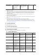
1.3 (1) Product Life Printer The value from (i) to (iii), whichever comes first. (i) 10,000 pages of color printing - Color: 7.5% duty per color pattern printing, A4 (ii) 1,200 discs of CD-R/DVD-R printing - On a basis of monthly print volume of approx. 20 discs (iii) 5 years of use (2) Print head 10,000 pages of color printing - Color: 7.5% duty per color pattern printing, A4 (3) Ink tank BCI-6BK: BCI-6C: BCI-6M: BCI-6Y: BCI-6PC: BCI-6PM: BCI-6R: BCI-6G: 1.
2. LIST OF ERROR DISPLAY / INDICATION Errors are indicated by the LED, and warnings are displayed on the monitor of the computer connected to the printer. 2.1 Operator Call Errors (LED Blinks in Orange) LED Blinks in orange 2 times Error No paper. / Pick up failure. (Sheet feeder unit) [1000] No CD-R tray [1001]*1 3 times Paper jam. [1300] 4 times No ink.
(Operator Call Errors - cont’d -) LED Error blinking in orange 11 times Automatic print head alignment failure [2500] Solution Remarks Press the Resume/Cancel button, and after confirming the following, perform print head alignment again: - Set an appropriate type and size of paper (plain paper, A4 or letter). - Check that the print head alignment pattern is properly printed (all ink ejected, no faint printing). - Check that the paper ejection slot is not exposed to light.
2.
printing. The paper output tray is in the CD-R printing position. (When printing on paper) *2 The paper output tray is in the CD-R printing position when the access cover is opened. When the paper output tray is set in the paper printing position and the access cover is closed, the warning is released. The paper output tray is in the paper printing position. The paper output tray is in the paper printing (When printing on CD-R) *2 position when the access cover is opened.
Unsatisfactory print quality (Troubleshooting by Symptom - cont’d -) Symptom Solution No printing, or no ink ejected. *3 Replace the - ink tank, - print head*2, - logic board ass’y*1, or - purge unit. Remove and re-install the print head, or replace the Printing is faint, or white lines - ink tank, appear on printouts even after - print head*2, print head cleaning. *3 Line(s) not included in the print - purge unit, or data appears on printouts. - logic board ass’y*1. Paper gets smeared.
3. REPAIR 3.1 Disassembling/Reassembling flow for main units The flow chart below shows decomposition in descending order, and assemble in ascending order. (Refer to the PIXUS 9900i/i9900/i9950 Parts Catalogue for details.) External (Access cover unit, Upper cover unit, Paper support unit, and Side covers, etc.
3.2 Notes on Service Part Replacement (and Disassembling / Reassembling) Service part Notes on replacement*1 Adjustment / settings Operation check After replacement: 1. Initialize the EEPROM. 2. Reset the waste ink counter (If the waste ink amount is 7% or more.) 3. Set the destination in the EEPROM. 4. Correct the media sensor. 5. Correct the CD-R and automatic print head alignment sensor. For details of 1 to 5, see Section 3.4. Adjustment / Settings, (6) Service mode. 6.
(Notes on Service Part Replacement and Disassembling / Reassembling - cont’d-) Service part Notes on replacement*1 Carriage Lift Part (QC1-2298, 2301, 2657, 4361, 4527, 4621, and 4632) Timing slit strip film (QC1-4520) Timing slit disk film (QC1-2484) - Upon contact with the film, wipe the film with ethanol. - Confirm no grease is on the film. (Wipe off any grease thoroughly with ethanol.) - Do not bend the film. Print head (QY6-0055) Adjustment / settings*2 Operation check At replacement: 1.
1. When ink tanks were installed upon receipt of the printer from users. 1) Remove the ink tanks. 2) Perform print head deep cleaning (for all colors) three times. * Through this step, ink in the print head is emptied. 3) Remove the print head. 4) Re-install the print head. 5) Re-install the ink tanks. 6) Perform service test printing, and check the print result. See Section 3.5. Verification Items (1) Service test print. 2. When ink tanks were not installed upon receipt of the printer from users.
Grease application 2 5 1 (Back side) Apply grease here 4 8 6 3 7 9 10 12 11 13 14 15 1 - 13
16 Part name Where to apply grease / oil Carriage slide plate (QC1-4517) Carriage shaft (QC1 -4516) Grease pad (QA4-0721) x 2 Shaft clip L (QC1-4654) Shaft clip R (QC1-4633) Adjust plate L Adjust plate L, Chassis 7 Adjust plate R, Chassis Lift base bushing (QC1-2301) Lift input gear (QC1-4527) Lift gear L (QC1-4560) Operation lever Lift gear R (QC1-4559) Gear box R Gear box L Paper guide flapper ass’y Note: 1 drop = 9 to 18 mg (4) Grease / oil name Grease / oil amount 1 Carriage unit sliding porti
Print head manual cleaning See “Standalone printer operation” below. Also available from the printer driver’s Maintenance tab. Print head deep cleaning Pick up roller cleaning Nozzle check pattern printing Perform from the printer driver utility. See “Standalone printer operation” below. See “Standalone printer operation” below. Print head alignment Perform from the printer driver utility. Print head replacement The print head is replaceable at the same position as for ink tank replacement.
dislocated during transportation, the paper lifting plate of the sheet feeder unit will be raised. 1) With the printer power turned off, while pressing the Resume/Cancel button, press and hold the Power button. (Do not release the buttons. The LED lights in green to indicate that a function is selectable.) 2) While holding the Power button, release the Resume/Cancel button. (Do not release the Power button.
In the media sensor correction mode, using the reference white PET paper and reference plain paper of the calibration media kit (QY9-0064), press the Resume/Cancel button the specified number of times in the table below, and press the Power button. The media sensor correction operation must be performed once each with the reference white PET paper and the reference plain paper.
Number of times of power-on S: Soft-power-on H: Hard-power-on xxxx Vx.xx D=xxx.
Check 2: Top of form accuracy Check 3: Straight lines Check 1 Nozzle check pattern Check 4 Halftone Check 5 (Result of CD-R/automatic print head alignment sensor correction) Check 6 (Media sensor correction: implemented or not implemented) 1 - 19
(2) EEPROM information print Print sample: (1)PIXUS 9900i (2)V1.02 (3)CN(USB1=1 USB2=0 1394=0) (4)USB=(200655) (5)D=004.
OTHER=xxxxx) MSPAGE (G1=xxxxx G2=xxxxx G3=xxxxx G4=xxxxx) Camera direct print port connection and removal count CDIN=xxxxx User print head alignment values UR(PMe=xx PMo=xx Re=xx Ro=xx BKle= xx BKlo= xx Ge= xx Go= xx PCe= xx PCo= xx C2e= xx C2o= xx M2e= xx M2o= xx Ye =xx Yo= xx M1e= xx M1o= xx C1e= xx C1o= xx) Print head alignment implementation (manual/auto/simple) REG (MN=x AT=x MG=x) Number of automatic powered on APON=x Number of automatic powered off APOFF=xxx Bidirectional print head alignment DIRREG(
4. PRINTER TRANSPORTATION METHOD This section describes the procedures for transporting the printer (for returning after repair, etc.). 1. Keep the print head and ink tanks installed in the carriage. (See Caution 1 below.) 2. Turn off the printer to securely lock the carriage in the home position. (When the printer is turned off, the carriage is automatically locked in place.) (See Caution 2 below.) Confirm that the paper lifting plate of the sheet feeder unit is raised.(See Caution 3 below.) 3.
Part 2 TECHNICAL REFERENCE
1. NEW TECHNOLOGIES (1) CD-R feeding mechanism For the i9950 model, the paper output tray serves as the CD-R tray feeder. (For the i9900 model, the paper output tray serves only its original function, as the model does not support CD-R printing.) 1. How to set the paper output tray when performing CD-R printing. By pressing the CD-R tray lever down, the paper output tray is raised to the CD-R printing position from the paper printing position.
2. How to set the paper output tray when performing paper printing By lifting the front of the paper output tray up slowly, the paper output tray returns to the paper printing position from the CD-R printing position. Problem If the paper output tray is in the CD-R printing position, when the access cover is opened with the printer powered on, the carriage does not move to the center.
(2) Independent cleaning For i9900/i9950 models, the print head consists of two blocks (C, M, Y and PM, R, BK, G, PC). As a result, it is possible to select either a specific block, or both blocks, for cleaning. For the i9100 model, which has only one block, it was possible only to perform bulk cleaning. The example print head composition is for the i9900/i9950 model. The i9900/i9950 print head consists of two blocks with eight colors (PM, R, BK. G, PC and C, M, Y, from left to right).
2. CLEANING MODE AND AMOUNT OF INK PURGED To prevent printing problems due to bubbles, dust, or ink clogging, print head cleaning is performed before the start of printing, except in the following cases: - Cleaning on arrival: Performed when the access cover is closed. - Cleaning by dot count: Performed after ejection of paper - Manual cleaning / deep cleaning: Performed manually. Group 1 includes BK/R/G/PC/PM, and Group 2 includes C/M/Y.
3. PRINT MODE 3.
(2) Standard gray scale printing (Paper types different than those for color printing only are listed.
(3) Borderless printing Paper type Custom setting value in driver UI High speed 5 <4 3 Print quality Resolution HxV (dpi) Print control Ink Custom Fine 2400×1200 4800×2400 4 passes, bidirectional 8 passes, bidirectional 8 colors 8 colors Print quality Photo Paper Plus Resolution HxV (dpi) Glossy Print control Ink Draft High 1200×1200 3 passes, bidirectional 6 colors 4800×2400 8 passes, bidirectional 8 colors Print quality Matte Photo Paper Resolution HxV (dpi) Print control Ink Print quality
(5) Camera Direct Printing PictBridge supporting mode Paper type Custom setting value in driver UI High speed 5 <4 3 -> 2 Print quality Photo Paper Pro (Fast Photo) High quality 1 High Resolution HxV (dpi) Print control Ink 4800×2400 8 passes, bidirectional 8 colors Photo Paper Plus Print quality Resolution HxV (dpi) Glossy (Photo / Default) Print control High 4800×2400 8 passes, bidirectional 8 colors Ink Bubble Jet Direct supporting mode Paper type Custom setting value in driver UI High sp
4. FAQ (Specific Problems and Solutions) No. 1 2 3 Occurrence Function Symptom level* B Print Depending on print results density, black streaks with 4 mm pitch or faint white streaks with 1-2 mm pitch may appear in gray-scale printing. B Print Green ink is not results ejected. B Print results The back side of paper is smeared in borderless printing. Condition Cause - Printing with gray-scale.
5. SPECIFICATIONS 5.1 Printer Specifications Type Paper feeding method Resolution Throughput Printing direction Print width Interface ASF stacking capacity Paper weight Detection functions Acoustic noise Environmental requirements Power supply External dimensions Weight Related standards (Proposed) (Printer, Adapter) Desktop serial color bubble jet printer Auto sheet feed (ASF) Front loading (CD-R printing only)*1 4,800 dpi x 2,400 dpi (Max.) Draft Standard Black (New Black) 16 ppm 4.
5.2 Print Head Specifications Print head Type Single head with 8 removable ink tanks (each color) Print head 768 nozzles in 2 vertical lines (1,200 dpi) for each color 2 pl ink droplet for all nozzles Ink color Dye-based black, cyan, magenta, yellow, photo cyan, photo magenta, red, green Ink tank BCI-6 BK/C/M/Y/PC/PM/R/G (dye-based) Weight (Net) Print head: approx.
Service specifications Service print head number The number of pages *Full waste ink error Period Service mode Service print pattern Service mode On EEPROM information printing (the number of A3/A3+ pages passed is displayed.) i9900/i9950 QY6-0055 15.75 k pages 3.75 years A4 (vertical) Yes i9100 QY6-0039 10 k pages 2.4 years A3 (Possible to be printed on A4 sized paper (horizontal) No Due to flash ROM, Due to mask ROM possible to rewrite use, exchange at the using tool. board level.
Part 3 APPENDIX
1.
2. CONNECTOR LOCATION AND PIN LAYOUT 2.
JCR1 (Print Head 1/3 [Carriage Unit]) No. Signal name Function 1 GND GND 2 ENCA CR encoder phase A 3 WIDTH CDR sensor signal 4 ENCB CR encoder phase B 5 EEPSK Head EEPROM serial clock signal 6 EEPDI Head EEPROM data signal 7 SNPOW Encoder power supply 3.3 V 8 VDD Head logic drive power supply 3.
JCR3 (Print Head 3/3 [Carriage Unit]) No. Signal name Function 1 to 8 VH2 Head drive power supply 20V 9 VDD Head logic drive power supply 3.3V 10 DIK Diode sensor cathode 11 DIA2 Diode sensor anode 3 12 GND GND 13 to 20 GNDH2 GND Input/Output Out Out Out In - JPOW1 (AC Adapter) No. Signal name 1, 2 VH 3 GND 4, 5 VM 6, 7 GND 8 VH_REMOTE 9 VM_SLEEP 10 +3.3V Input/Output In In Out Out In Function Head power supply GND Motor power supply GND VH control signal VM control signal Logic power supply +3.
JIF1 (IEEE1394 I/F) No. Signal name 1 VBUS 2 GND 3 TPB14 TPB1+ 5 TPA16 TPA1+ Function IEEE1394: IEEE1394: IEEE1394: IEEE1394: IEEE1394: IEEE1394: VBUS GND TPB1-signal TPB1+signal TPA1-signal TPA1-signal Input/Output NC Bus Bus Bus Bus JLFT1 (Lift Cam Sensor [Photo Interrupter]) No. Signal name Function 1 VSEN_5V Sensor power supply 5V 2 GND GND 3 SNS_LIFT_UP CD-R lift-up sensor signal Input/Output Out In JINK1 (Ink Sensor [Platen Unit]) No.
JASFS1 (ASF Motor [Sheet Feeder Unit]) No. Signal name 1 ASFBASF motor phase B2 ASFAASF motor phase A3 ASFB ASF motor phase B+ 4 ASFA ASF motor phase A+ Function Input/Output Out Out Out Out JPGS1 (Purge Sensor [Purge Unit]) No. Signal name Function 1 SNS_PG PURGE sensor signal 2 GND GND 3 VSEN_5V Sensor power supply 5V Input/Output Out In JPES1 (PE Sensor) No.
No.
PRINTED IN JAPAN (IMPRIME AU JAPON) 3-8 CANON INC.