
Service manual


(10/25)
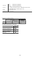
4. REPAIR
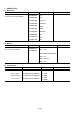
4.1 Notes on Service Part Replacement (and Disassembling/Reassembling) in Asia
Service part Notes on replacement Adjustment/settings Operation check
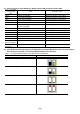
Logic board ass’y
(QM2-2841)
- Detach the logic board
ass’y about one
minute after removing
the power cord to
prevent the logic board
ass’y from being
damaged. (to
discharge the
accumulated electricity
in the capacitor)
- If a waste ink amount
is more than 7%,
replacement of the ink
absorber is necessary.
After replacement:
1. Initialize the
EEPROM.
2. Reset the waste ink
counter.
3. Set the destination in
the EEPROM.
See 4.2 SERVICE
MODE.
4. Perform the print
head alignment in
the user mode.
- EEPROM print
- Service test print
- Printing via an
USB connection
- Camera Direct
print
Operation panel unit
(QM2-3327)
After replacement:
1. Check the buttons /
the LCD
See 4.2 SERVICE
MODE.
Absorber kit
(QY5-0418)
Platen ink absorber
(QC1-6014)
After replacement:
1. Reset the waste ink
counter.
See 4.2 SERVICE
MODE.
- Service test print
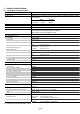
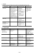
4.2 SERVICE MODE
Item Timing Objective Remarks
Service test print
- Model name
- Rom version
- USB serial number
- Waste ink amount
At printer operation
checking or parts
replacement
Operation checking See Service mode
operation procedures.
Load A4, LTR, or more
large sized paper.
Print sample: See
APPENDIX 1: SHIPMENT
INSPECTION PATTERN 1.
EEPROM reset At Logic board replacement Reset except for the
followings.
- USB serial number
- Destination setting
- Waste ink counter
See Service mode
operation procedures.
Waste ink counter reset At waste ink absorber
replacement
Waste ink counter reset See the waste ink counter
reset procedures.
(For Asia only)
Destination setting At Logic board replacement Destination setting See Service mode
operation procedures &
Destination setting
procedures.
(For Asia only)
Button / LCD checking At Operation panel
operation checking
(such as Operation panel
unit replacement)
Button / LCD operation
checking
See Button / LCD checking
operation procedures.
(For Asia only)