Release Notes WITE32 Version 3.
WITE32 Release Notes Version 3.20 Table of Contents Chapter 1 Introduction .................................................................................................................................4 1.1 Updated PRML Chip Drivers ................................................................................................................................................ 4 1.2 Updated Revision Numbers of Head Amplifier and Head Stack Drivers .......................................................
WITE32 Release Notes Version 3.20 4.3.1 Spindle Rotation Direction Warning on 1701A+ ......................................................................................................... 51 4.3.2 Disabling Linear Scale Correction for Guzik 1701B Spinstand .................................................................................. 51 4.4 2 MFlux/s Lower Limit of System Frequency for RWA 2000 Series................................................................................... 51 4.
WITE32 Release Notes Version 3.20 CHAPTER 1 INTRODUCTION The release 3.20 of WITE32 incorporates the new features and the bug fixes introduced after the release 3.11. This document uses the release notes for the WITE32 version 3.11 as a base line for a comparison. 1.1 Updated PRML Chip Drivers ! Note: With the WITE32 version 3.20 you must use only the version 3.20 of the drivers for RC6600, 88C7500P PRML channels (Chip Adapter 2000 board), and 88C7500M PRML channel (Chip Adapter 4000 board).
WITE32 Release Notes Version 3.20 CHAPTER 2 NEW HARDWARE SUPPORTED IN WITE32 2.1 Spinstand Control Box Models SCB-V2002A and SCB-V2002B Two new spinstand control box models are supported starting from WITE32 version 3.20. The SCB-V2002A and SCB-V2002B control boxes function with any Guzik V2002 spinstand. The new control boxes are interchangeable with the previous control box model SCB-V2002, use the same external cable connection diagrams, and are similar in operation.
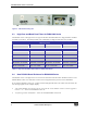
WITE32 Release Notes Version 3.20 Figure 2: ANA 2002A Analog Box 2.3 High Pass and Band Pass Filters for RWA-2000 Series The WITE32 version 3.20 supports two new types of the filters for RWA-2000 series: high pass filters and band pass filters (see Table 2). The band pass filter is the combination of a high pass filter and a low pass filter.
WITE32 Release Notes Version 3.20 2.5 New Head Amplifiers The following head amplifiers are initially supported in WITE32 version 3.20: New Head Amplifiers SR1970 SR1971 81G5114P SR1641 SR1644 SR1670 SR1673 SR1970 TLS26A954AA SR1972 TC7547 (not compatible with WITE32 version less than 3.20) 2.6 New Head Stacks The following new head stacks are initially supported in WITE32 version 3.
WITE32 Release Notes Version 3.20 CHAPTER 3 NEW FEATURES INTRODUCED IN WITE32 3.1 Guzik Servo Revision 3 Starting from the WITE32 version 3.20, the RWA of the 2000 series equipped with the Servo Revision 3 hardware operates only in Servo Revision 3 mode. Refer to the manual Guzik Servo Revision 3 For RWA-2000 Series (P/N 02-107283-03) for the description of the Guzik Servo Revision 3. WITE32 version 3.20 does not support a combination of Servo-3 RWA and Servo-2 spinstand.
WITE32 Release Notes Version 3.20 3.3.1 Head Recovery Procedure for Comb Loader and Head Stack Tooling In the case of emergency on the V2002 spinstand with a head comb loader or a head stack tooling, the tested head or a head stack remains on a disk and needs to be unloaded manually.
WITE32 Release Notes Version 3.20 3.3.1.1 Head Recovery Procedure for Head Comb Loader The Head Recovery tab of the WDCP2002 dialog box has two frames: the Configuration frame and the Emergency Head Unloading Instructions frame. • The Configuration frame contains the Head Recovery Procedure For read-only field, which displays the type of the head loading mechanism currently installed on the spinstand.
WITE32 Release Notes Version 3.20 • The Emergency Head Unloading Instructions frame displays the recovery instructions with the corresponding control items, which let you to confirm the instruction completion: Step 1 Reset emergency conditions. Press the Reset Emergencies button to clear a crash emergency and an air emergency. Step 2 If the head is on the disk, select the Head On Disk radio button. Otherwise select the Head Out of Disk radio button.
WITE32 Release Notes Version 3.20 3.3.1.2 Head Recovery Procedure for Head Stack The Head Recovery tab of the WDCP2002 dialog box has two frames: the Configuration frame and the Emergency Head Unloading Instructions frame. • The Configuration frame contains one read-only text box. The Head Recovery Procedure For text box displays the type of the head loading mechanism currently installed on the spinstand.
WITE32 Release Notes Version 3.20 • The Emergency Head Unloading Instructions frame displays the recovery instructions with the corresponding control items, which let you to confirm the instruction completion: Step 1 Reset emergency conditions Press the Reset Emergencies button to clear a crash emergency and an air emergency. Step 2 If head on the disk, select Head On Disk choice, otherwise select Head Out of Disk choice.
WITE32 Release Notes Version 3.20 3.3.2 Revision 2 of V2002 Spinstand Head Alignment The new revision of the Head Alignment test for the V2002 spinstand is implemented in the WITE32 version 3.20. The Head Alignment Revision 2 calculates the coordinates of the disk center more accurately. The new test finds the track, written by a reference head, with the accuracy improved from 100 µm to 10µm. Note: The Head Alignment Revision 2 can be used with Servo Revision 3 RWA only.
WITE32 Release Notes Version 3.20 • • The Working Zone frame allows you to specify a working zone to be erased and the position where the service track will be written. The Track Number text box Specifies the track number, where service track will be written. The Zone Width text box Specifies the width of the working zone of the test. This zone will be erased and then used for the track detection stroke movements.
WITE32 Release Notes Version 3.20 To switch the Lock Motors mode on or off, select or clear the Enable Lock Motors Mode check box on the Motor Params tab. This tab is a part of the Spinstand Parameters tab set of the WDCP2002 dialog box (see Figure 6). Note: If you perform the reset, when the Lock Motors mode is enabled, the software will show the warning message “Linear Motors are locked by software”. You need to switch the Lock Motors mode off in order to reset the spinstand.
WITE32 Release Notes Version 3.20 In the WITE32 version 3.20, four following items are displayed on the drop-down list in the Disk Chuck Type dialog box: • Unknown disk chuck • Fixed clamping • Vacuum clamping • Air clamping You must select the disk chuck, which is installed on your spinstand before you will start the machine. Note: Only the chuck with the fixed clamping was supported in the WITE32 version 3.11. 3.
WITE32 Release Notes Version 3.20 Figure 8: Chip Adapter User Interface The control items in the Chip Config dialog are combined on seven tabs and on a menu bar. 3.5.1 Main Menu Bar The menu bar of the Chip Config dialog box includes the following menus: • The File menu • The Actions menu • The Script menu • The Options menu The File pull-down menu includes the following commands: The Load Zone/Setup command 18 Loads zone setup parameters of the PRML chip from the WITE32 database.
WITE32 Release Notes Version 3.20 The Save Zone/Setup command Saves zone setup parameters of the PRML chip to the WITE32 database. The Load Registers from File command Loads register values from the file, created by the Save Registers to File command. The Save Registers to File command Saves current register values to a file. The Compare Registers with File command Compares current register values with the register values saved in the file, created by the Save Registers to File command.
WITE32 Release Notes Version 3.20 The Sweep Metric command Varies the bit field value and measures the metric selected on the Metric tab. Displays the measurement results in a graphical form on the Bit Field Sweep graph (see section 3.5.2.3). The Run Default Optimization command Executes the default optimization sequence specified in the chip driver (see section 3.5.2.4). The Custom Optimization command Executes the custom optimization sequence configured on the Optimization tab (see section 3.5.2.4).
WITE32 Release Notes Version 3.20 The Pages menu 3.5.2 Shows and hides the following tabs: • The Adaptive tab • The Metric tab • The Optimization tab • The Functions tab • The Driver tab • The Scripting tab Control Tabs Use the controls located on the following tabs to configure the PRML chip parameters, to analyze the PRML chip response, to optimize the PRML chip performance, and to create a Visual Basic script.
WITE32 Release Notes Version 3.20 3.5.2.1 Bit Fields Tab On the Bit Fields tab (see Figure 9) you can monitor and modify the chip register values in two formats: as a register view in the Register frame and as a bit field view on the Bit Fields panel. The register view is a direct representation of a physical register, so you can access each chip register as a single unit.
WITE32 Release Notes Version 3.20 The following items are on the Bit Fields tab: The Bit Field Groups panel Use the list shown in this panel to select the bit field group you want to be displayed on the Bit Fields panel. Note: The <> item is not a group name. When you select it, all bit fields are displayed on the Bit Fields panel simultaneously. The Bit Fields panel Displays all bit fields from the bit field group selected on the Bit Field Groups panel.
WITE32 Release Notes Version 3.20 The Address text box Use this box to specify the register physical address in either decimal of hexadecimal format. Note: A numeric value with 0x prefix will be assumed as a hexadecimal. Otherwise it will be assumed as a decimal value. The Address scroll buttons Click one of the buttons to increment or decrement by one the value in the Address text box. The Data(Bin) text box Use this box to specify the register value in binary format.
WITE32 Release Notes Version 3.20 3.5.2.2 Adaptives Tab The Adaptives tab (see Figure 10) displays in a graphical form how the values of one or more adaptive registers change from sector to sector during the read operation. It allows you to analyze the chip adaptation circuit behavior in dynamics. Figure 10: Adaptives Tab The following items are on the Adaptives tab: The Adaptive Registers panel Shows the list of all adaptive registers defined by the chip driver.
WITE32 Release Notes Version 3.20 The Reset Registers button Click this button to reload the current values of the registers selected on the Adaptive Registers panel to the chip. The Set Average Values button Click this button to load the mid-value of the registers selected on the Adaptive Registers panel to the chip. A mid-value is defined as an arithmetic average of the minimum and the maximum register values. EXAMPLE: For a four-bit register with a range 0…15 the mid-value is 7.
WITE32 Release Notes Version 3.20 3.5.2.3 Metric Tab The Metric tab (see Figure 11) provides you with a plot of the metric result versus values of a selected bit field. The metric is a special function, which reflects the quality of a particular system setting. By using a metric you can evaluate the system performance and find the best configuration for the specific range of parameters. See the WITE32 PRML Chip Driver Development Kit Programmer’s Guide for more information.
WITE32 Release Notes Version 3.20 The “…” button Click this button to open the Find Bit Field dialog box (see Section 3.5.4). The From text box In this box enter the bit field starting value. The To text box In this box enter the bit field ending value. The Step text box In this box enter the bit field value increment step. The Action frame contains the following items: The Metric combo box Select the metric from the drop-down list in this box.
WITE32 Release Notes Version 3.20 3.5.2.4 Optimization Tab On the Optimization tab (see Figure 12) you can optimize the chip for the best performance. The optimization procedure is a sequence of optimization blocks, which are implemented in the chip driver. See the WITE32 PRML Chip Driver Development Kit Programmer’s Guide for more information.
WITE32 Release Notes Version 3.20 The following items are on the Optimization tab: The Custom Optimization Sequence table The table includes the following columns: • The Block column displays the names of the optimization blocks defined by the chip driver • The Optimize column specifies whether the block will be included in the optimization sequence or not. To include a block in the optimization sequence, in the Optimize column select the check box corresponding to the block.
WITE32 Release Notes Version 3.20 The Run Default Optimization button Click this button to execute the Default Optimization Sequence specified in the chip driver The Run Custom Optimization button Click this button to execute a Custom Optimization Sequence. The # of Iterations edit box Specify the number of iterations for execution of the Optimization Sequence.
WITE32 Release Notes Version 3.20 3.5.2.5 Functions Tab Using the Functions tab (see Figure 13) you can select a custom functions defined by the chip driver, specify its parameters, execute the function, and see results. See the WITE32 PRML Chip Driver Development Kit Programmer’s Guide for more information. Figure 13: Functions Tab The following items are on the Functions tab: The Functions panel 32 Displays the custom functions defined by the chip driver • The Name column shows the function names.
WITE32 Release Notes Version 3.20 The Parameters: Input Parameters panel Displays the input parameters for the function selected on the Functions panel. • The Name column shows the parameter names. • The Value column shows the parameter values. This is the only column, where you can change the value. Note: • The Parameters: Output Parameter panel The Run button Note: To change a value, switch to the edit mode by double clicking the value.
WITE32 Release Notes Version 3.20 3.5.2.6 Driver Tab On the Driver tab (see Figure 14) you can check the driver and device information and configure some of the system parameters. Figure 14: Driver Tab The following items are on the Driver tab: The Driver Information panel Displays the chip driver information. The Device Information panel Displays the chip adapter board information.
WITE32 Release Notes Version 3.20 The Encoding Ratio frame contains the following control: The Ratio combo box Select from the drop-down list in this box, which encoding ratio the system have to apply. The Signal Outputs frame contains the following items: The Scope Point 1 combo box Select from the drop-down list in this box, which signal you want to observe at the Scope Point 1 BNC connector of the Analog Box 2002A front panel.
WITE32 Release Notes Version 3.20 3.5.2.7 Scripting Tab On the Scripting tab (see Figure 15) you can develop and run Visual Basic script.
WITE32 Release Notes Version 3.20 The following items are on the Scripting tab: The Software Object selection combo box at the top-left side Shows the list of all Software Objects, registered in the scripting environment and accessible from a script. Each object provides a list of methods and events for programmatic access. The Object Event selection combo box at the top-middle side Shows the list of all Events available for the selected Software Object.
WITE32 Release Notes Version 3.20 Clear the Output panel content. • The PRML_CHIP_ADAPTER object to access all chip interfaces (see the PRML Chip Driver Development Kit. Software Interfaces manual for the description of available PRML_CHIP_ADAPTER object interfaces) 3.5.4 Find Bit Field Dialog Box You can use the Find Bit Field dialog box (see Figure 16) to quickly locate a specific bit field on the tabs.
WITE32 Release Notes Version 3.20 The Address text box Select from the drop-down list or type in this box, the address for searching a bit field by the address. Note: The Group text box A numeric entry without 0x prefix will be treated as a decimal value. You can use a group name as one of the criteria for a bit field searching. To do this, select from the drop-down menu here or type in this box, the name of the bit field group you want to look for the bit filed.
WITE32 Release Notes Version 3.20 CHAPTER 4 WITE32 MODIFICATIONS 4.1 Guzik V2002 Spinstand The following tests and features are modified in the WITE32 version 3.20 40 • The XY Alignment test (see Section 4.1.1) • The Y-Limit Adjustment test (see Section 4.1.2) • The Spinstand Parameters dialog box (see Section 4.1.3) • The Product Parameters dialog box and the procedure for editing the product parameters (see Section 4.1.
WITE32 Release Notes Version 3.20 4.1.1 XY Alignment Test The graphical output dialog box of the XY Alignment test (see Figure 17) now shows the detected track as a complete circle instead of an arc.
WITE32 Release Notes Version 3.20 4.1.2 Y-Limit Adjustment Test Starting from the WITE32 version 3.20: 1. The Y-Screw Limit Adjustment test for V2002 spinstand supports the cartridge and media sets listed in Table 3: Cartridge Part Number Media Size (Inch) 80-701773 / 701774 1.0 80-701838 / 701839 2.5, 3.5 80-702057 / 702058 1.0, 2.5 80-702138 2.5 80-702191 / 702192 3.5 80-702210 / 702211 3.0 80-702313 / 702314 1.0, 2.5 80-702315 / 702316 1.0, 2.5 80-702356 / 702357 1.0, 2.
WITE32 Release Notes Version 3.20 2. A new step is added to the Y-Screw Limit Adjustment procedure (see Figure 18). The new step Moving YStage From Spindle helps you to move the Y-stage manually away from the spindle and do not hit the sensors limiting the stage movement. If the Y-stage touches any one of these sensors, the spinstand is not able to perform a reset. The step is the last one in the procedure.
WITE32 Release Notes Version 3.20 2. The Disk Product Parameters frame in the Spinstand Product Parameters dialog box has a new layout (see Figure 19). All controls in this frame are the same as they were in the WITE32 version 3.11. 3. The parameters of 3.5 Inch media will be used for the product parameters initialization when the DDT file is not found or not specified. 4.1.
WITE32 Release Notes Version 3.20 4.1.6 Micro Actuators Tab in V2002 Product Parameters Dialog Box In order to clarify the meaning of the micro actuator parameters, the Micro Actuators configuration tab is redesigned. In addition to the previously available controls, it contains the micro actuator connection diagram and two new text boxes. Figure 20: Micro Actuator Parameters in the V2002 Product Parameters Dialog Box The parameters of the CCW and CW micro actuators can be configured independently.
WITE32 Release Notes Version 3.20 this entry. This entry can be automatically updated by the Micro Actuator Stroke test, which measures the actual range. • The Voltage Range (A) Max text box specifies the positive voltage applied to a Micro Actuator device. • The Voltage Range (B) Min text box specifies the negative voltage applied to a Micro Actuator device. • The Voltage Range (C) Middle text box specifies the middle point voltage (in Volts).
WITE32 Release Notes Version 3.20 4.2.1 Head Bandwidth Selection for RWA Models With Servo-3 In order to support Servo-3 for low frequency heads the head bandwidth selection feature is introduced. To specify the head bandwidth the Head Bandwidth frame is added to the Servo Control dialog box (Control | Servo).
WITE32 Release Notes Version 3.20 Figure 22: Incorrect Head Bandwidth Warning During Servo Calibration 4.2.2 Reset Index Skew Control in the Servo Erase Configuration Dialog Box A new control Reset Index Skew check box is added to the Erase Servo Configuration dialog box (see Figure 23). The index skew is the delay between the spinstand index and internally generated RWA index (refer to WITE32 System Configuration User’s Guide for detailed information about the index skew feature).
WITE32 Release Notes Version 3.20 Figure 23: Reset Index Skew 4.2.3 Servo Calibration Dialog Box Modifications The Servo Calibration dialog box is changed in the WITE32 version 3.20. Figure 24 shows the Servo Calibration dialog box as it was in WITE32 version 3.11. Figure 25 shows the same dialog box of WITE32 version 3.20. The differences between the old and the new dialog boxes are highlighted and enumerated by the reference numbers.
WITE32 Release Notes Version 3.20 1 3 5 2 Figure 24: Old Servo Calibration Dialog Box 4 3 5 Figure 25: New Servo Calibration Dialog Box 4.2.4 Cool Down Delay in Servo Calibration A cool down delay is added between the band erase operation and the measurements in the Servo Calibration operation if the Erase Track Before Calibration option is enabled. Without this timeout, a continuous write operation performed during the band erase overheats the head amplifier and the head cartridge.
WITE32 Release Notes Version 3.20 4.3 Guzik 1701 Spinstand Family The following modifications were implemented for Guzik 1701A+ and 1701B spinstands: 4.3.1 • Spindle Rotation Direction Warning on 1701A+ (see Section 4.3.1) • Disabling Linear Scale Correction for Guzik 1701B Spinstand (see Section 4.3.
WITE32 Release Notes Version 3.20 4.5 Alternative Overwrite Test Modifications In the WITE32 version 3.20, the Alternative Overwrite test has some new features designed to make measurements suitable for Perpendicular Recording. Both the test algorithm and the test setup dialog box are changed. Figure 28 shows the Alternative Overwrite test dialog box as it was in WITE32 version 3.11. Figure 29 shows the same dialog box of WITE32 version 3.20.
WITE32 Release Notes Version 3.20 The differences between the old and the new dialog boxes are highlighted and enumerated by the reference numbers. The following sections describe the modifications in order of increasing the reference numbers. 4.5.
WITE32 Release Notes Version 3.20 • Do Not Trim — do not perform track trimming. • Erase Positive — perform track trimming by positive erasure, as in prior WITE32 versions. • Erase Negative — perform track trimming by negative erasure. • System Erase — perform track trimming using system erase options, which are accessible through the Control | Band Erase dialog. For perpendicular recording system erase must be set AC Erase, thus enabling AC erasure for track trimming. 4.5.4 1.
WITE32 Release Notes Version 3.20 Figure 30: Save Error Info Pull-Down Menu in WITE32 Error Message Dialog Box The Save Error Info pull-down menu has the following three menu items: Save to File Allow you to save the detailed error information into a text file. When this menu item is selected, the Windows standard file selection dialog appears. In this dialog you can specify the file name, in which you want to save the error information.
WITE32 Release Notes Version 3.20 4.9 Tests and Modules no Longer Supported in WITE32 1. The RCE32 module is discontinued and removed from the WITE32 version 3.20. Its functionality is implemented in the newest PRML channel drivers (see sections 3.4 and 3.5). Please, contact Guzik Technical Support for details. 2. The obsolete 747 Servo Track Profile Test is removed from the 747 Test module. 4.
WITE32 Release Notes Version 3.20 4.11 Miscellaneous 1. A special feature is implemented in the WR Offset test to help you to select the better Track Profile Range parameters. If the test is unable to measure the WR Offset or/and the Track Width, it calculates the Track Profile Range parameters (From, To, and Step) based on the preliminary profile measurements. The test displays a message with the suggested From, To, and Step values.
WITE32 Release Notes Version 3.20 7. The accuracy and stability of PW measurements were improved for all WITE32 tests if the RWA input signal is noisy and asymmetrical. This improvement is done for RWA-2000 series. 8. A new option Hide Grading Result Window is added to the Grading system. Figure 31: Hide Grading Result Window Check Box The Hide Grading Result Window check box 58 When it is checked, the final grading result window will not be displayed at the end of the production test.
WITE32 Release Notes Version 3.20 CHAPTER 5 FIXED BUGS The following bugs were discovered in WITE32 version 3.11 or earlier, and fixed in WITE32 version 3.20. The description below explains the bug behavior as it appears in WITE32 version 3.11. 5.1 V2002 Spinstand 1. The XY Alignment test may hit Y-limit sensor (screw). 2. The XY Alignment test may fail if head negative and position skew angles are not the same. 3. The XY Alignment test may fail if a tooling has non zero angle. 4.
WITE32 Release Notes Version 3.20 4. 5. 5.3 WDCP crashes after the following sequence of actions: • Select Head Stack check box in the Spinstand Parameters dialog box (Parameters | Spinstand Parameters… menu item of the Spinstand Alignment Program WDCP). • Press Save Data in EPROM button. • Close WDCP and reset spinstand. • Run WDCP in standalone mode.
WITE32 Release Notes Version 3.20 5.5 Tests and Measurements 1. The Spectral Integral SNR test does not use Load/Unload Parameters defined in the spinstand setup when the Use Spin Stand Load/Unload Parameters option is selected in the test setup. The test loads/unloads a head on the OD radius for measuring an unloaded head noise. 2.
WITE32 Release Notes Version 3.20 14. In the Gated Stability mode the Amplitude Stability and the Pulse Width Stability tests set the write gate wrongly – full size instead of 50% of a full size – if the Always Full Size option is enabled in the Control | Gate and Track Format dialog. 15. The Spectrum Analyzer frequency response correction was applied only to the Spectrum Analyzer, Spectral SNR, and Spectral Integral SNR tests.
WITE32 Release Notes Version 3.20 12. An error message "PG: Cannot load FPGA for 318130 Fab: X Assy: X " pops up intermittently on WITE32 loading. 13. WITE32 does not turn off head amplifier power for testers with UP7 if you close WITE32 without stop device or run single test (not production sequence) from soft button on the Operator Panel.
WITE32 Release Notes Version 3.20 CHAPTER 6 KNOWN ISSUES 6.1 Servo-3 RWA and Servo-2 Spinstand Incompatibility Notification WITE32 version 3.20 does not support a combination of Servo-3 RWA and Servo-2 spinstand. The following error message is displayed if WITE32 software detects such configuration: "Servo-2 spinstand and Servo-3 RWA are incompatible. Please, contact Guzik technical support". 6.