USE AND CARE MANUAL DUAL FUEL RANGE 30” 36” 48” & 60” OPEN BURNER / SEALED BURNER MODELS: COB / CSB
A SPECIAL MESSAGE TO CUSTOMERS Dear Valued Customer, Congratulations on making a smart choice! You have joined an elite group of cooking enthusiasts who demand only the very best from their appliances. A Capital Cooking appliance promises years of enjoyment and maximum performance, allowing cooks everywhere to create culinary memories that last a lifetime. Because of the unique features found in our appliances, we urge you to read this manual thoroughly before installation and use.
TABLE OF CONTENTS A SPECIAL MESSAGE TO CUSTOMERS ................................................................................................................1 TABLE OF CONTENTS..............................................................................................................................................2 WARNINGS AND GENERAL SAFETY ......................................................................................................................4 GENERAL SAFETY PRECAUTIONS .............
MEAT PROBE: ............................................................................................................................................... 26 MEAT PROBE SOCKET:................................................................................................................................ 26 ROTISSERIE MOTOR SOCKET: ................................................................................................................... 26 ROTISSERIE SPIT ROD AND FORKS: ............................
WARNINGS AND GENERAL SAFETY WARNING! If the information in this manual is not followed, fire or explosion may result causing property damage, personal injury or death WARNING! Do not install or use this product near water or outdoors, for example, near a kitchen sink, in a wet basement or near a swimming pool WARNING! Disconnect Power before installing. Prior to turning power ON, verify that all gas controls are in the OFF position. ANSI/NCSBCS A225.1 or with local codes as applicable.
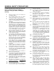
GENERAL SAFETY PRECAUTIONS To reduce the risk of fire, electric shock, serious injury or death when using your appliance, follow basic safety precautions, including the following: 1. Read the provided use and care manual before operating this appliance. 2. Keep packaging materials away from children. Plastic sheets and bags can cause suffocation. 3. If your range is found to be damaged upon receipt, contact your dealer or builder immediately.
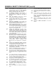
GENERAL SAFETY PRECAUTIONS (cont’d) 31. USE CAUTION to ensure that drafts like those from forced air vents or fans do not blow flammable materials toward the flames or push the flames so that they extend beyond the edges of the pot. 32. TO MINIMIZE ACCIDENTS, position handles of utensils inward so that they do not extend over adjacent work areas, cooking areas or the edge of the range. 33. HOLD THE HANDLE of the pan to prevent movement of the utensil when stirring food. 34.
COB / CSB DUAL FUEL RANGE MODELS 36” DUAL FUEL MODELS 30” DUAL FUEL MODELS CSB304 – Sealed Burner COB304 – Open Burner CSB366 – Sealed Burner COB366 – Open Burner 48” DUAL FUEL MODELS CSB362G2 – Sealed Burner COB362G2 – Open Burner 60” DUAL FUEL MODELS CSB488 – Sealed Burner COB488 – Open Burner CSB484BG – Sealed Burner COB484BG – Open Burner CSB604GB2 – Sealed Burner COB604GB2 – Open Burner CSB484G2 – Sealed Burner COB484G2 – Open Burner CSB484G2 – Sealed Burner COB484G2 – Open Burner CSB604BB2
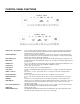
CONTROL PANEL FUNCTIONS 30”, 36” RANGE OVEN CONTROLS 48”, 60” RANGE OVEN CONTROLS CANCEL (LEFT / RIGHT) Button: Turns off current cooking mode with a single press. It is also used to lock and unlock the control panel when desired. Dual Oven Ranges (48” and 60”) have a LEFT CANCEL and RIGHT CANCEL button, which will cancel the specified oven function. CONVECTION Button: Turns the Convection Fan On or Off when cooking for convection modes.
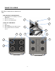
RANGE TOP LEGEND Note: These components are common for all sizes. MOIST WATER SYSTEM RESERVOIR 1. Moist Water Reservoir (Always Located at Right Rear) 2. Moist Reservoir Cover 3. Moist Cover Retaining Chain RANGE TOP COMPONENTS 4. Grate 5. Burner Cap 6. Burner Spill Ring (Sealed Burner Only) 7.
RANGE FEATURE LEGEND 1. 2. 3. 4. 5. 6. 7. 8. 9. 10. 11. 12. 13. 14. 15. 16. 17. 18. 19. 20. 21. 22. 23. 24. 25. 26. 27.
RANGE FEATURES DEFINED 1. Mode Icons: A light above the selected Mode will illuminate to show which oven mode is being used. All lights (except PROBE) will light up when Mode selection is started. A single mode will be highlighted when the Mode Selector Dial is rotated and Mode is selected. 2. Range Top Grates Professional style heavy duty porcelain coated cast iron grates are easy to clean and securely hold all sizes of pots and pans to provide a stable cooking surface. 3.
RANGE FEATURES DEFINED (continued) 15. Rotisserie Spit Rod The Rotisserie Spit Rod is used in combination with the Rotisserie Forks to hold food when cooking in Rotisserie mode. 16. Meat Probe The Meat Probe plugs into the Meat Probe Socket in the wall of the oven and into the food being cooked. The Meat Probe can then be set to the desired food temperature for cooking. 17.
USING YOUR RANGE INITIAL OVEN SETUP CLOCK When powered up and prior to pressing any buttons the clock will flash 12:00 and will increase each minute. To set the oven clock press the CLOCK button on the control panel once. The clock will blink indicating it is ready to be set and the AM or PM icon will be displayed. Set the correct time by rotating the TEMP/TIME knob on the right side of the control panel clockwise to increase the time and counter clockwise to decrease the time.
OVEN HEATING MODES DEFINED Your Oven features cooking modes for practically all forms of home cooking. PRE-HEAT Most recipes call for an oven to be heated to a particular temperature before you start cooking. This heating of the oven is the Pre-Heat mode and uses high intensity heat from the top, bottom, and rear of the oven to quickly and evenly heat the oven. The Convection Fan is also used during Pre-Heat to rapidly distribute the heat throughout the oven.
OVEN HEATING MODES DEFINED (continued) SELF CLEAN Self Clean is a special heating function that raises the oven temperature to levels that will burn most food byproducts to ash. It is a 3 hour heating cycle but due to the extreme heat generated, the oven door is automatically locked when the cycle is started.
SETTING THE OVEN Know which oven mode is to be used and the temperature setting. DOUBLE: If setting a Double Oven either the RIGHT or LEFT oven must be selected by pressing one of the control panel buttons. o The selected oven button will be indicated by a small light in the center of the button. o Each oven must be set separately and can use independent modes. o If SELF CLEAN is used in either oven, the other oven will not be functional until the SELF CLEAN cycle is complete.
TURNING THE OVEN OFF To cancel a cooking mode and turn the oven Off use the CANCEL button. o DOUBLE: The LEFT CANCEL button will cancel only the LEFT oven functions. The RIGHT CANCEL button will only cancel the RIGHT oven functions. The CANCEL button will not turn off the oven lights. Use the LIGHT button. SECURING THE OVEN CONTROL The oven control can be locked into a Secure mode to prevent accidentally turning the oven by children or when cleaning.
SETTING TIMERS The Timers are timers only and do not affect oven functions. Your oven has two independent countdown timers: TIMER 1 and TIMER 2. The Timers may each be set from 5 seconds to 11 hours 50 minutes. To set, press either TIMER 1 or TIMER 2 buttons (they each have the same functions). Rotate the TIMER/TEMP dial clockwise to increase the timer setting. Press the START button to begin the timer countdown. NOTE: If START is not pressed within 10 seconds, the timer will be cancelled.
SPECIAL FUNCTIONS SELF CLEAN WARNING: Remove all racks, cooking vessels, utensils, meat probe and all other items from the oven prior to cleaning. IMPORTANT: Clean excess spillage, grease and other cooking byproducts from the oven prior to Self Cleaning. WARNING: Do not line the oven with aluminum foil or other materials. They may melt, burn or cause permanent damage to the oven. WARNING: Do not touch the outer surfaces of the oven during the Self-Clean cycle as the oven may be hot.
SPECIAL FUNCTIONS CONVECTION (Standard on All Dual Fuel Range Ovens) The CONVECTION button turns the oven Convection Fan on during a cooking mode providing an additional four modes of cooking. CONVECTION used in combination with BAKE, DELICATE, BAKE, BROIL, or ROAST uses the same heat sources as the standard set mode but evenly moves the heated air throughout the oven. When cooking is complete and a mode is cancelled, the CONVECTION fan will automatically turn off.
MOIST (30” or 36” Oven or PRIMARY Oven only on 48” or 60”) The MOIST feature adds a small amount of water to the oven every minute when cooking, resulting in moister cooked foods. Water is stored in a Water Reservoir behind the door and flows into an Evaporation Tray below the convection baffle inside the oven. IMPORTANT: ONLY USE DISTILLED WATER TO FILL THE RESERVOIR. Regular tap water will cause a buildup of minerals in the orifice of the moist system and may cause clogging.
SPECIAL FUNCTIONS PROBE PROBE allows the oven to monitor the food temperature as it cooks and stops cooking when the food is done. The Meat Probe is inserted into the food to monitor the internal temperature. When the food is done, the cooking mode will change to HOLD mode for two hours. The PROBE function is used in conjunction with a cooking mode set to the recipe cooking temperature. WARNING: The PROBE function cannot be used with BROIL or SELF CLEAN modes to prevent damage to the Meat Probe.
SPECIAL FUNCTIONS DELAY COOK Your oven can be set to start cooking at a desired time by presetting a cooking mode, temperature, and setting a start time in DELAY COOK. WARNING: When using DELAY COOK, always maintain food safe habits and be extremely careful of access to the oven by children or adults who may be injured or cause damage by a live oven. WARNING: Do not use DELAY COOK for foods subject to spoiling (dairy products, eggs, uncooked poultry, etc.
At the end of a TIMED COOK mode, the oven will change from the cooking mode to HOLD mode. HOLD mode will lower the oven temperature setting to 150° F and will remain on for 2 hours. SABBATH MODE Sabbath mode will turn off beepers, disable oven lights, will maintain constant readouts of “SAb” in the temperature readout zone, and will allow oven temperature to be changed without changing displays, disables oven lights.
TIPS General Always center your cookware within the oven from front to back and side to side to ensure even heating. Darker containers will absorb more heat and will provide a darker or crisper crust while lighter pans and vessels will reflect more heat and provide a more uniform heat. Use low sided or flat cooking vessels, such as cookie sheets, when cooking with convection and even heat is desired around the food.
CARE AND MAINTENANCE WARNING: Do not touch the interior surfaces of the oven during use. After use, make sure these surfaces have had sufficient time to cool before touching them. WARNING: Do not clean the oven door gaskets. The door gaskets are essential for a good seal of the oven. Care is to be taken during cleaning to prevent rubbing, damaging, or moving the gasket from its installed position.
USING THE RANGETOP BURNERS CAPITAL RANGE TOP BURNERS Your new gas range is equipped with the latest in burner technology and is configured with either the Capital Open Burne r system or the Capital Sealed Burn er system . Both system s are the m ost powerful standard burners of their kind on th e m arket today. CAPITAL OPEN BURNERS CAPITAL SEALED BURNERS All Open Burner ranges are equipped with one small pan burner at the back left position on the range top and all others rated at 23.
Note: If the Igniter continues to click after the burner has been lit, turn the knob to a setting other than LITE, or HI. If the problem still persists, please call our Service Hotline at 866-402-4600. BURNER SETTINGS The rangetop burner valves have infinite settings with no fixed positions on the control knobs between HI and SIMMER. To turn the rangetop burner on, push in the control knob and turn it counterclockwise to the "LITE" position. An audible clicking sound will be heard.
USING THE GRILL FEATURE CAUTION! U s e e x t r e m e c a r e w h e n p l a c i n g t h e g r i l l components into the grill compartment. Avoid hitting the ceramic igniter that could break, preventing operation of the grill. Do not leave the grill unattended while in use.
USING THE GRILL FEATURE (cont’d) CAUTION! Use extreme care when placing the grill components into the grill compartment. Avoid hitting the ceramic igniter which can break and prevent the grill from operating Do not leave the grill unattended while in use. Do not use charcoal briquettes, ceramic plates, or coals of any kind. After removing all packaging materials, check to be certain that the grill components are correctly assembled in the grill box.
USING THE THERMO GRIDDLE DESCRIPTION: The built in griddle is made of non rusting 3/8" thick stainless steel. This produces a surface that is easy to clean and never rusts. The griddle has a aluminized steel straight tube burner that is lit by a hot surface igniter. The griddle should pre heat for five to ten minutes. A chopping block is available as an accessory and purchased separately. It is sized to fit on top of the griddle surface when Range top is not in use. The burner is rated at 18,000 BTU/HR.
CLEANING AND MAINTENANCE AT THE END OF THE CLEAN CYCLE CAUTON: The interior of the oven will still be at baking temperature when the lock light turns off and the oven door can be opened. Use caution as the oven may be hot enough to cause burns. The Clean cycle takes hours to complete. The LOCK light turns off once the cycle has finished and the oven has cooled to 525° F. The door latch will open automatically after the automatic Door Lock completes its 30 sec, cycle to the OPEN position.
CLEANING AND MAINTENANCE (cont’d) CLEANING IGNITERS Wipe with a water-dampened cotton swab. Be careful not to damage the igniter. (See illustration). CLEANING CONTROL KNOBS - RANGETOP AND OVEN These are made of die-cast metal with plastic inserts for easier gripping. They can be cleaned in hot, soapy water. To remove the Knobs from the control panel, grasp the knob and pull straight forward. Wash, do not soak. Rinse and dry thoroughly.
CLEANING CHART: Always start by selecting the mildest cleaner according to the kind of soil and the material soiled. To prevent marring the stainless steel finish, always apply the cleaners in the direction of the grain. Rinse and dry immediately to avoid water marks. Use clean applicators, i.e. soft cloths, sponges, or paper towels for cleaning and scouring. The use of brand names in the chart is intended only to indicate a type of cleaner. This does not constitute an endorsement.
35 Check oven temperature and mode setting Verify that the desired oven has been set for cooking on a double by pressing RIGHT or LEFT as appropriate Oven is improperly set Opposite oven set on a double oven Clean with mild detergent when racks and/or are cool. Rollers or tracks may be dirty Racks may have been left in oven during SELF CLEAN Light lenses may be dirty Racks are hard to move Lights do not illuminate well Clean lenses when oven is cool with water and mild detergent.
SERVICE INFORMATION If none of the above has occurred, contact our customer service department at (866) 402-4600. Before you call for service, please have the following information available: Model Number Serial Number Date of Installation Copy of Receipt or Invoice A brief description of the problem Your satisfaction is our top priority. If the problem persists or is not resolved to your satisfaction by our service consultant, please write to us or fax us a letter at: Capital Cooking Equipment, Inc.
WARRANTY One (1) year full parts and labor, covers the entire unit. ONE (1) Year full parts and labor covers entire product with the exception of painted or decorative parts listed below*. (Light bulbs covered for 60 days after installation). Standard shipping only. Expedited shipping will be at customer expense. *Painted and decorative parts will be warranted for 90 days from date of original purchase. Any damages or defects must be reported within this timeframe.
USE AND CARE MANUAL CONNOISSEURIAN SERIES 30” 36” 48” & 60” DUAL FUEL RANGE MODELS: COB / CSB 38
Dimensional Diagrams: Product Dimensions: SINGLE FRONT VIEW DOUBLE FRONT VIEW OVEN TOP VIEW OVEN SIDE VIEW 39
PLANNING THE INSTALLATION 1. Plan the intended installation location by verifying that sufficient cabinet size and clearances are available. 2. Check that electrical power is available or can be established at the installation location and that all local codes can be met. 3. To provide the optimal operation of your appliance, the oven should be installed in a location that will minimize drafts created by doors, windows, ventilation outlets, etc. 4.
RANGE INSTALLATION 41
PLEASE READ ENTIRE INSTRUCTION BEFORE PROCEEDING. UNPACKING AND HANDLING 1. 2. 3. 4. Move the oven as close to the point of installation as possible prior to removing packing materials to prevent damage. Remove all packing materials from inside the oven and any protective plastic on the outside of the oven. Read and retain all instructions before installation and use and after installation as a reference. The units are heavy. Plan sufficient manpower and use caution when lifting the unit.
ELECTRICAL WIRING INSTALLATION (cont’d): STEP 1: ELECTRICAL INSTALLATION STANDARD WIRING (FOUR WIRE CONNECTION) 1. Each wire must be individually connected to the household supply wire. 2. Connect the Green appliance ground wire to the Green household ground wire from the junction box. 3. Connect the appliance Black L1 wire to the household Black L1 wire from the junction box. 4. Connect the appliance White Neutral wire to the household White neutral wire from the junction box. 5.
INSTALLATION: STEP 2: VENTILATION REQUIREMENTS HOOD PLACEMENT: WARNING: DO NOT obstruct the flow of combustion and ventilation air to the unit. For best smoke elimination, the lower edge of the hood should be installed a minimum of 30" to a maximum of 36" above the range cooking surface. CAPITAL Hood blower speeds are variable to reduce noi s e and l os s of heat ed or ai r -c ondi t i oned household air when maximum ventilation is not required.
INSTALLATION (cont’d): STEP 3: CABINET PREPARATION T h e ra n g e i s a f re e st a n d i n g u n i t .
INSTALLATION – CASTER HEIGHT ADJUSTMENT: CASTER ADJUSTMENT The range has casters only at the rear of the range, To adjust the height of the range use a flat head screwdriver and crescent wrench to turn the threaded rod.
INSTALLATION (cont’d): IMPORTANT INSTALLATION INFORMATION The thickness of the wall or floor may require use of longer screws, available at your local hardware store. In all cases at least one (1) of the bracket mounting screws must be fastened to solid wood or metal on each side. Use appropriate anchors when fastening the mounting bracket to any material other than hardwood or metal. STEP 4: INSTALLING ANTI-TIP DEVICE For all Ranges, an anti-tip device MUST be installed as per these instructions.
INSTALLATION (cont’d): WARNING: ELECTRICAL SHOCK HAZARD! Use extreme caution when drilling holes into the wall or floor. There may be concealed electrical wires located behind the wall or under the floor. Identify the electrical circuits that could be affected by the installation of the Anti-Tip Device, then turn off power to these circuits. Failure to follow these instructions may result in electrical shock or other personal injury.
INSTALLATION (cont’d): CAUTION! The appliance must be isolated from the gas supply piping system by closing its individual manual shut-off valve during any pressure testing of the gas supply piping system at test pressures equal to or less than 112 psig (3.5kPa.). The Appliance and its individual shut off valve must be disconnected from the gas supply piping system during any pressure testing of the system at test pressures in excess of 1/2 psig (3.5kPa.).
Note to Customer. Please make sure installer signs each item on this checklist, explains each item before leaving and explains the range operation to you thoroughly. INSTALLER CHECKLIST FINAL CHECKLIST All internal packing materials removed. Check below grates and grill pans and inside the ovens Cabinet cutouts and installation have met the requirements of these instructions. Oven electrical connections follow instructions and meet local codes.
OPEN BURNER FLAME ADJUSTMENT PROCEDURE Note: This procedure is not required for units with sealed range top burners PREPARATION For safety purposes, turn off power and gas to the range while removing and installing the burner parts. Turn off all ventilation hoods, heating & air conditioning, and close windows near the appliance to prevent breezes from interfering during adjustment. Carefully clean the metal tip of the igniter electrode with alcohol and a lightly abrasive cleaning pad or toothbrush.
OPEN BURNER FLAME ADJUSTMENT PROCEDURE Simmer Adjustment ADJUST SIMMER FLAME To adjust the simmer flame you will need a flat head screwdriver with a 3/32” maximum diameter shaft and a length of at least 2-1/4” and pliers. IMPORTANT: Turn off air conditioning, fans, and ventilation hoods and close windows to prevent breezes around the burners when making these adjustments. They can affect burner function. Set the burner to be adjusted to Simmer. Remove the knob by carefully pulling the knob straight out.
DOOR REMOVAL AND REPLACEMENT PROCEDURE 53
SERVICE INFORMATION Before contacting customer service: Verify that the circuit breaker has tripped or the fuse has been blown. Is there a power outage in the local area? If none of the above has occurred, contact our customer service department at (866) 402-4600. Before you call for service, please have the following information available: Model Number Serial Number Date of Installation Copy of Receipt or Invoice A brief description of the problem Your satisfaction is our top priority.
WARRANTY ONE (1) Year full parts and labor covers entire product with the exception of painted or decorative parts listed below*. (Light bulbs covered for 60 days after installation). Standard shipping only. Expedited shipping will be at customer expense. *Painted and decorative parts will be warranted for 90 days from date of original purchase. Any damages or defects must be reported within this timeframe.
THESE SPECIFICATIONS ARE FOR PLANNING PURPOSES ONLY. CONSULT WITH AN AUTHORIZED TECHNICIAN FOR YOUR SPECIFIC INSTALLATION DETAIL REQUIREMENTS. FOR THE MOST UP TO DATE INFORMATION, CONTACT CAPITAL COOKING EQUIPMENT, INC. INDICATING THE MODEL NUMBER. WE RESERVE THE RIGHT TO CHANGE THESE SPECIFICATIONS OR DESIGN WITHOUT NOTICE. THE POWER OF PERFORMANCE TM Capital Cooking Equipment, Inc. 13211 E. Florence Ave. Santa Fe Springs, CA 90670 USA 866.402.4600 Toll Free 562.903.1167 Fax MADE IN USA www.