
Service manual

Allgemeiner Teil / General Section GV 30…, GV 50…
1 - 6 GRUNDIG Service
Servicehinweise
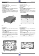
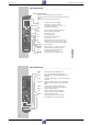
1. Entfernen der Gehäuseteile
1.1 Gehäuseoberteil
– 2 Schrauben
A
und 2 Schrauben
B
herausdrehen (Fig. 1).
– Gehäuseoberteil abnehmen.
1.2 Frontblende
– 3 Rasthaken
C
(Fig. 2) auf der Geräteunterseite lösen.
– Frontblende an der Unterseite nach vorne klappen und die Blende
an den oberen Haken
D
(Fig. 3) aushängen.
Montagehinweis:
– Beim Aufstecken der Frontblende auf den Geräterahmen ist die
Cassettenklappe zu öffnen. Der Cassettenklappenhebel (Pos. 0500,
siehe Seite 6-1) befindet sich dadurch vor der Cassettenklappe in
richtiger Position.
Service Instructions
1. Removing the Cabinet Parts
1.1 Cabinet Top
– Undo 2 screws
A
and 2 screws
B
(Fig. 1).
– Remove the cabinet top.
1.2 Front Panel
– Release 3 clamps
C
(Fig. 2) on the cabinet bottom.
– Turn the lower edge of the front panel towards the front and detach
the panel from the upper clamps
D
(Fig. 3).
Reassembly:
– When attaching the front panel to the cabinet frame, open the
cassette compartment door. In this way, the door opening lever
(Pos. 0500, see page 6-1) is positioned correctly in front of the
cassette compartment door.
Fig. 1 Fig. 2
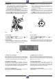
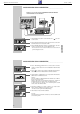
2. Ausbauhinweise
2.1 Laufwerk
– Steckverbindungen (Fig. 3, CN181 / CN201 / CN351) zum Laufwerk
lösen.
– Arretierung
E
(Fig. 3) des Cassettenschachtes an den beiden
Aussparungen
F
nacheinander lösen und diesen dabei bis An-
schlag nach innen schieben.
– 2 Schrauben
G
(Fig. 4) herausdrehen.
Hinweis: Der Schraubendreher sollte einen dünnen Schaft haben,
da die linke Schraube schwer zugänglich ist. Sollte kein geeigneter
Schraubendreher zur Verfügung stehen, ist der Cassettenschacht
auszubauen (siehe Kapitel "Laufwerk" Punkt 8.1). Anschließend
sind die 2 Schrauben
G
herauszudrehen.
– 2 Schrauben
H
(Fig. 3) und 2 Schrauben
I
(Fig. 2) herausdre-
hen.
– Laufwerk waagerecht nach oben herausnehmen.
2. Disassembly Instructions
2.1 Drive Mechanism
– Unplug the the plug-in connections (Fig. 3, CN181 / CN201 / CN351)
to the drive mechanism.
– Disengage the locking lever
E
(Fig. 3) of the cassette mechanism
successively at the two cutouts
F
and slide the mechanism inwards
to the stop.
– Undo 2 screws
G
(Fig. 4).
Note: The screwdriver should have a thin shank because access to
the left screw is difficult. If a suitable screwdriver is not available,
remove the cassette compartment mechanism (see "Drive Mecha-
nism", point 8.1) and subsequently undo the 2 screws
G
.
– Undo 2 screws
H
(Fig. 3) and 2 screws
I
(Fig. 2).
– To remove the Drive Mechanism, lift it in horizontal position.
Fig. 3 Fig. 4
B
A
A
C
I
G
G
E
F
D D
H
CN181
CN351
CN201
O
O
K
K