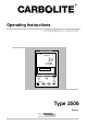
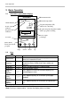
Operating Instructions Temperature Controller EUROTHERM OP1 RUN/HLD °C 23 1200 % 96.0 A/MAN RUN/HOLD 3508 Ack Type 3508 English 1 MC19-1.
3508 Controller Note: For the purposes of this manual the Eurotherm 3504 range is functionally identical to the 3508 range. 2 MC19-1.
508 Controller Contents 1.1 1.2 2 Basic Operation 2.1 2.2 3 Operator Level 1 - No Program Running Operator Level 1 - Program Running Supervisor Level 2 Controller Fault 8.1 9 Digital Communications – RS232 Digital Communications – RS485 Comms Address Alarm Option Remote Input and Output (Analogue Communications) Program segment output Navigation Diagrams 7.1 7.2 7.
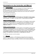
3508 Controller Introduction to the Controller and Manual 1.1 Using This Manual This manual aims to explain how to set up and operate the Eurotherm 3508 series of controllers; it must be read in conjunction with the product main manual. Due to the complex nature of furnace or oven control the use of technical terms throughout this manual is unavoidable. Explanations of these terms can be found in the ‘Glossary of Terms’ at the back of this manual.
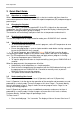
Basic Operation 2 Basic Operation 2.1 Controller Layout (Home display) Measurement units EUROTHERM ALM OP1 °C RUN HLD Alarm indicator Measured temperature 23 Power output indicator Setpoint temperature (SP) when basic controlling 1200 Program status indicators. Program Setpoint temperature (PSP) when a program is running % 96.0 Not used A/MAN 3508 Ack Runs, Holds, Resets the current program Page 2.
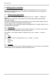
Basic Operation 3 Quick Start Guide 3.1 Operation as a simple controller When switched on the controller goes through a short test routine and then shows the measured temperature. Below it is shown the setpoint temperature (SP) and percentage of power output. 3.2 Changing the Setpoint Press up down to select the required SP.
Controller Fault and Glossary of Terms 2. Press up to select level 2. After a short pause the display will show “Access Pass code”. 3. Press up or down to enter the pass code 9, Pass is momentarily displayed. After a short pause the display will return to home, the controller is now in level 2. When Level 2 operations have been completed the supervisor must return to Level 1 manually. It is not necessary to enter a code when going from a higher level to a lower level. To Return to Level 1: 1.
Basic Operation 4 Setting up the controller Before using the controller (or during its lifetime) certain parameters may have to be set, depending on specific requirements. To do this the Controller must be set to supervisor Level 2, see section 3.5. 4.1 Maximum output power setting Press page until Control Output Hi is displayed. Press up or down to adjust the value. Depending on the furnace or oven model, the maximum power output setting may be accessible or locked.
Basic Operation 5 Programming 5.1 Programming Notes Programs can be created in Level 1 or Level 2 of the 3508. For the P10 and P25, new programs can be created while the current program is running. To avoid unwanted heating at the end of a program, set the controller SP temperature to zero before running a program. All new unused programs show only 1 segment of type End. The minimum number of segments for a program is 2. The second being an End type. Ramp-to-setpoint control.
Notes For a Step segment Holdback delays continuation to the next segment until the step target is reached. The Holdback Type can be set as follows: Low Applies to heating only High Applies to cooling only Band Applies to both heating and cooling Off Holdback is off To set the Holdback type press page twice, then press scroll until the display shows Holdback Type for each segment and press up or down to set. The default setting for Holdback is Off. 5.
Notes Program number On P10 or P25 models press up or down to select a new program number. The display will show that new programs have only one segment. Holdback Value Press scroll until the display shows “Holdback Value”. If required: Press up or down to set a value. This value will be used in any segment where a Holdback Type is set. Ramp Units These apply to Rate segments only. Press scroll until the display shows “Ramp Units”.
Notes 5.6 Running a Program The current program can be started from the home display by pressing RUN/HOLD. Or by pressing page once, then scroll once (twice for P10 and P25), then press up or down 5.7 To pause (hold) a program Press RUN/HOLD or Press page until Program Status Reset appears Press scroll until the cursor moves to Reset Press up or down to select Hold RUN/HLD will be displayed 5.
Notes Program setpoint (PSP) Current Segment Type. Step and Call segments are instant, so are only flashed on the screen, unless Holdback is operating on that segment. Target Setpoint Segment Rate For Rate, Time and Step segments only Cycles left Program Time Left Program hold with holdback If a holdback value has been set (see “Programming”) and the program goes into a hold state, the green HLD indicator will flash, until the measured temperature catches up.
Notes 14 MC19-1.
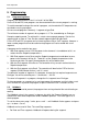
Notes 5.13 Program Example 1 The following sequence of entries creates and runs the program shown graphically below. 1. 2. 3. 4. 5. 6. 7. 8. 9. 10. Turn the controller SP down to ‘0’ by pressing down . Press page until Prog, Segments Used is displayed. On P10 or P25 models press up or down to select a new program number, (a program with only 1 segment). Press scroll until Holdback Value is displayed. Default ‘0’ degrees. Press scroll until Ramp Units is displayed.
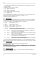
Notes 5.14 Program Example 2 The following sequence of entries creates and runs the program shown graphically below. 1. Turn the Setpoint to ‘0’ by Pressing down 2. Press page until Prog, Segments Used is displayed. On P10 and P25 models press up or downto select a new program number, (a program with only 1 segment). 3. Press scroll until Holdback Value is displayed. Press up or downto set to ‘5’ degrees 4. Press scroll until Ramp Units is displayed.
Basic Operation 6 Options Because options can be ordered in a variety of combinations and for a variety of purposes, exact instructions are not given here. The full Eurotherm manual may be required to determine customer parameter settings. To reveal or hide parameters in the controllers it is necessary to go into configuration modes, a security code is needed. Please consult Carbolite. 6.
Notes To change the address value access the level 2 list. In level 2 press the page key until the COMMS parameter is displayed. Press up 6.4 Alarm Option When an alarm board is fitted with free contacts for customer use, the contacts are taken to a panel plug on the control panel, wired as indicated: Controller n/o contacts 2A fuse supply load The purpose of the 2 amp fuse is to protect the internal circuitry from excess electrical current.
Basic Operation 7 Navigation Diagrams 7.
Notes 7.
Notes 7.3 Supervisor Level 2 To enter Level 2 Home display Access Press & hold for 3 seconds Press to select Level 2 Goto Level 1 Access Pass code Press to select code 9 Home display (Level 1) (Level 2) Level 2 Current program page Home display Customer ID nr Control Output Hi Units C ProgStat Program nr See level 1 diagrams Controller identity when MC19-1.
Basic Operation 8 Controller Fault 8.1 Fault Code Diagnostic Table Error Code S.br Explanation Actions Temperature sensor failure Replace the Furnace or Oven Temperature Sensor 9 Glossary of Terms Home display PID Parameter Segment Program Measured temperature Setpoint temperature (SP) Program setpoint temperature (PSP) The first display of the controller screen, to which it returns when no keys are pressed. Proportional, Integral, Derivative: the control system used by the controller.
Notes MC19-1.
Notes For preventive maintenance, repair and calibration of all Furnace and Oven products, please contact: Carbolite Engineering Services Telephone: +44 (0)1433 624242 Fax: +44 (0)1433 624243 Email: service@carbolite.com Carbolite, Parsons Lane, Hope, Hope Valley, S33 6RB, England. Telephone: +44 (0)1433 620011 Fax: +44 (0)1433 621198 E-mail: info@carbolite.com MC19 – 1.