EM24-DIN PFA, PFB & X models COMMUNICATION PROTOCOL Version 4 Revision 0 December 03th, 2012
Index 1.1 1.2 Introduction ...........................................................................................................................................3 MODBUS functions ...............................................................................................................................3 1.2.1 1.2.2 1.2.3 1.2.4 1.2.5 1.3 Application notes ...................................................................................................................................6 1.3.1 1.
Energy management 1.1 Introduction The RS485 serial interface supports the MODBUS/JBUS (RTU) protocol. In this document only the information necessary to read/write from/to EM24-DIN has been reported (not all the parts of the protocol have been implemented). For a complete description of the MODBUS protocol please refer to the “Modbus_Application_Protocol_V1_1a.pdf” document that is downloadable from the www.modbus.org web site. 1.
Energy management Response frame (incorrect action) Description Physical address Function code Exception code CRC Length 1 byte 1 byte 1 byte 2 bytes Value 1 to F7h (1 to 247) 83h 01h, 02h, 03h, 04h (see note) Note Possible exception : 01h: illegal function 02h: illegal data address 03h: illegal data value 04h: slave device failure 1.2.2 Function 04h (Read Input Registers) This function code is used to read the contents of a contiguous block of input registers (word).
Energy management Response frame (incorrect action) Description Physical address Function code Exception code CRC Length 1 byte 1 byte 1 byte 2 bytes Value 1 to F7h (1 to 247) 86h 01h, 02h, 03h, 04h Note Possible exception : 01h: illegal function 02h: illegal data address 03h: illegal data value 04h: slave device failure 1.2.
Energy management 1.3 1.3.1 Application notes RS485 general considerations 1. To avoid errors due to the signal reflections or line coupling, it is necessary to terminate the bus at the beginning and at the end (inserting a 120 ohm 1/2W 5% resistor between line B and A in the last instrument and in the Host interface). 2. The network termination is necessary even in case of point-to-point connection and/or of short distances. 3.
Energy management 2 TABLES 2.1 Data format representation In Carlo Gavazzi instruments The variables are represented by integers or floating numbers, with 2’s complement notation in case of “signed” format, using the following: Format INT16 UINT16 INT32 UINT32 UINT64 IEEE754 SP IEC data type INT UINT DINT UDINT ULINT Description Integer Unsigned integer Double integer Unsigned double int Unsigned long integer Single-precision floating-point Bits 16 16 32 32 64 32 Range -32768 .. 32767 0 ..
Energy management 2.
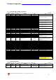
Energy management 2.5 Current tariff MODBUS: read only mode with functions code 03 and 04 limited to a word at a time Modicom address 300770 2.6 Physical address 0301h Length (words) 1 VARIABLE ENG. UNIT Current tariff Data Format UINT 16 Table 2.
Energy management 2.9 2.9.1 Programming parameter tables Password configuration menu MODBUS: read and write mode Modicom address 304353 2.9.2 Physical address 1100h Length (words) 1 Table 2.9-1 VARIABLE ENG. UNIT PASSWORD Data Format UINT 16 VARIABLE ENG. UNIT Type of application Data Format UINT 16 Notes Minimum valid value: 0d Maximum valid value: 9999d If the value is outside the limits the instrument considers that the value is equal to 0.
Energy management 2.9.5 Selector menu MODBUS: read and write mode Modicom address 304357 304358 304359 304360 2.9.6 Physical address 1104h 1105h 1106h 1107h Length (words) 1 1 1 1 Table 2.9-5 VARIABLE ENG.
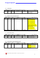
Energy management 2.9.9 User configuration menu MODBUS: read and write mode Modicom address 304365 304366 304367 Physical address 110Ch 110Dh 110Eh Length (words) 1 1 1 Table 2.9-9 VARIABLE ENG. UNIT ID code of user 1 ID code of user 2 ID code of user 3 Data Format UINT 16 UINT 16 UINT 16 Notes Value min = 1 Value max = 9999 2.9.10 Digital input configuration menu MODBUS: read and write mode Table 2.9-10 Modicom address 304386 Physical address 1121h Length (words) 1 VARIABLE ENG.
Energy management 2.9.11 PT and CT configuration menu MODBUS: read and write mode Table 2.9-11 Modicom address 304397 Physical address 112Ch Length (words) 2 VARIABLE ENG. UNIT Current transformer ratio Data Format UINT 32 304399 112Eh 2 Voltage transformer ratio UINT 32 Notes Value Value Value Value min max min max = = = = 10 (CT=1,0) 600000 (CT=60000.0) 10 (VT=1,0) 60000 (VT=6000.0) 2.9.12 Serial number MODBUS: read only mode Table 2.
Energy management 3.1 Modifications from Version 1 Revision 0 Added NON MID models management 3.2 Modifications from Version 2 Revision 0 Modified table 2.8-1 (added Carlo Gavazzi identification code for AV6 models) 3.3 Modifications from Version 3 Revision 0 Corrected table 2.9-2 (added application “D” in column “Notes”) 3.