
User Manual

Energy management
EM24-DIN PFA, PFB & X models - Communication Protocol
3
1.1 Introduction
The RS485 serial interface supports the MODBUS/JBUS (RTU) protocol. In this document only the
information necessary to read/write from/to EM24-DIN has been reported (not all the parts of the
protocol have been implemented).
For a complete description of the MODBUS protocol please refer to the
“Modbus_Application_Protocol_V1_1a.pdf” document that is downloadable from the www.modbus.org
web site.
1.2 MODBUS functions
These functions are available on EM24-DIN:
• Reading of n “Holding Registers” (code 03h)
• Reading of n “Input Register” (code 04h)
• Writing of one “Holding Registers” (code 06h)
• Diagnostic (code 08h with sub-function code 00h)
• Broadcast mode (writing instruction on address 00h)
IMPORTANT:
1) In this document the “Modbus address” field is indicated in two modes:
1.1) “Modicom address”: it is the “6-digit Modicom” representation with Modbus function code
04 (Read Input Registers). It is possible to read the same values with function code 03 (Read
Holding Registers) replacing the first digit (“3”) with the number “4”.
1.2) “Physical address”: it is the “word address” value to be included in the communication
frame.
2) The functions 03h and 04h have exactly the same effect and can be used indifferently.
3) The communication parameters are to be set according to the configuration of the instrument
(refer to EM24-DIN instruction manual)
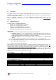
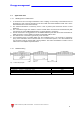
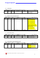
1.2.1 Function 03h (Read Holding Registers)
This function is used to read the contents of a contiguous block of holding registers (word). The
Request frame specifies the starting register address and the number of registers to be read. It is
possible to read maximum 11 registers (words) with a single request, when not differently specified.
The register data in the response message are packed as two bytes per register (word), with the binary
contents right justified within each byte. For each register, the first byte contains the high order bits
(MSB) and the second contains the low order bits (LSB).
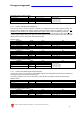
Request frame
Description Length Value Note
Physical address 1 byte 1 to F7h (1 to 247)
Function code 1 byte 03h
Starting address 2 bytes 0000h to FFFFh Byte order: MSB, LSB
Quantity of registers (N word)
2 bytes 1 to 10h (1 to 11) Byte order: MSB, LSB
CRC 2 bytes
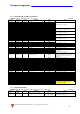
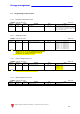
Response frame (correct action)
Description Length Value Note
Physical address 1 byte 1 to F7h (1 to 247)
Function code 1 byte 03h
Quantity of requested bytes 1 byte
N word * 2
Register value
N*2 bytes
Byte order: MSB, LSB
CRC 2 bytes