
User Manual


Energy management
EM24-DIN PFA, PFB & X models - Communication Protocol
6
1.3 Application notes
1.3.1 RS485 general considerations
1. To avoid errors due to the signal reflections or line coupling, it is necessary to terminate the bus at
the beginning and at the end (inserting a 120 ohm 1/2W 5% resistor between line B and A in the
last instrument and in the Host interface).
2. The network termination is necessary even in case of point-to-point connection and/or of short
distances.
3. For connections longer than 1000m or if in the network there are more than 160 instruments (with
1/5 unit load as used in EM24-DIN interface), a signal repeater is necessary.
4. For bus connection it is suggested to use an AWG24 balanced pair cable and to add a third wire for
GND connection. Connect GND to the shield if a shielded cable is used.
5. The GND is to be connected to ground only at the host side.
6. If an instrument does not answer within the “max answering time”, it is necessary to repeat the
query. If the instrument does not answer after 2 or 3 consecutive queries, it is to be considered as
not connected, faulty or reached with a wrong address. The same consideration is valid in case of
CRC errors or incomplete response frames.
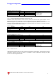
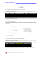
1.3.2 MODBUS timing
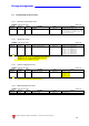
Fig. 1 : 2-wire timing diagram
Timing characteristics of reading function: msec
T response: Max answering time 500ms
T response: Typical answering time 40ms
T delay: Minimum time before a new query 3.5char
T null: Max interruption time during the request frame 2.5char