MODEL GASG201 GAS GUARD OPERATIONS MANUAL PO Box 715 Marietta, OH 45750 800-648-3042 740-373-6809 Fax 740-374-3760 www.caronproducts.com service@caronproducts.
Dear Valued Customer: Thank you for purchasing CARON Products & Services equipment. We appreciate your business and look forward to being your preferred supplier of controlled environment equipment products in the future. At CARON, we are committed to continuous quality improvement. Our goal is to supply our customers with highly reliable equipment at a fair price. In order to openly monitor our performance, we would appreciate your feedback on our products and services.
WARRANTY INFORMATION Please review this section before requesting warranty service. At CARON, one of our primary goals is to provide customers with high levels of personal service and top quality products, delivered on time, and backed by technical service and support for the life of the product. Before contacting us for warranty service, please be aware that there are repairs that are not covered under warranty. These include: 1) Calibration of control parameters. 2) Damage resulting from improper use.
NOT COVERED: Cost of express shipments such as Federal Express, UPS Next Day Air, UPS Second Day Air, or any other express shipment charges. Any customer modifications of this equipment, or any repairs undertaken without the prior written consent of CARON, will render this limited warranty void. CARON is not responsible for consequential, incidental or special damages. In no event will CARON be responsible for damages more than the price of the product.
TABLE OF CONTENTS Section 1 – Equipment Overview…………………………………………….. 7 Section 2 – Installation…………………………………………………………. 8 Connecting a Gas Supply Connecting Electrical Power Equipment Operation Section 3 – Spare Replacement Parts ……………………………………… 11 Section 4 – Specifications …………………………………………………….
INTERNATIONAL SYMBOLS AND DEFINITIONS ? Help i Information Warning of hazardous area Warning of dangerous electric voltage Earth (ground) protective conductor WARNINGS Local government may require proper disposal Model GASG201 Operations Manual Page 6 of 13 Rev D 01/18/2009
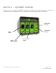
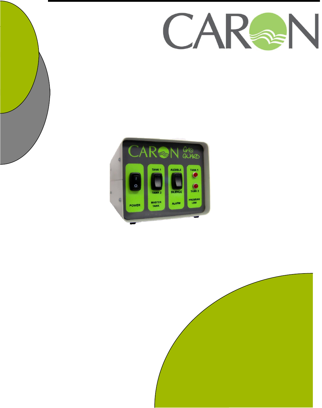
SECTION 1 – EQUIPMENT OVERVIEW Thank you for purchasing CARON equipment! Before using the equipment, familiarize yourself with key components of the product and thoroughly read this manual.
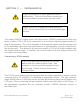
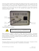
SECTION 2 -- INSTALLATION High concentrations of many gases can cause asphyxiation. The use of monitors and alarms is recommended for areas where gas can collect. Model GASG201 is designed to work with N2 or CO2. Do not connect this unit to a combustible gas source. The model GASG201 Stand Alone Gas Guard from CARON is designed to allow two tanks of either CO2 or N2 to be connected to an incubator requiring approximately 15 psig of gas pressure.
Once the cylinder regulators are installed and adjusted on each tank, connect the outlet of the regulator on Tank 1 to the hose barb fitting labeled Tank 1 on the back of the unit using the tubing and clamps provided. Repeat the process for Tank 2. The gas outlet connection on the back of the unit can then be connected to the incubator using the supplied tubing and clamps. Turn on the regulated gas supplies and check the connections closely for leaks.
The factory default “master tank” is Tank 1. When the appropriate gas pressure is supplied to both tanks, the master tank will always be used as the gas source. The unit will swap from the master tank to the alternative tank whenever a low gas pressure condition is detected. The alarm switch is used to disable the audible alarm when a low gas condition is detected. The audible alarm can be silenced while a new tank is installed by selecting the silence position.
SECTION 3 – SPARE/REPLACEMENT PARTS General Part Number FUS-151 SOL-137 SWT-127 POW-109 TUB-145 CLM-132 Description 2 Amp Fuse 3 Way Solenoid Gas Pressure Switch 24V DC Power Supply 3/8” Tygon Tubing Tubing Clamps Model GASG201 Operations Manual Page 11 of 13 Rev D 01/18/2009
SECTION 4 – SPECIFICATIONS Model Tank 1 Inlet Pressure Range Tank 1 Inlet Trip Point Tank 2 Inlet Pressure Range Tank 2 Inlet Trip Point Exterior Dimensions Exterior Construction Electrical Shipping Weight GASG201 Up to 30 psig 10-12 psig Up to 30 psig 10-12 psig 5” W x 6” H x 10” D Painted, Cold Roll Steel 115V, 60 Hz, 15 Amp, NEMA 5-15P Plug 10 lbs Specifications are subject to change without notice.
SECTION 5 – ELECTRICAL SCHEMATICS Model GASG201 Operations Manual Page 13 of 13 Rev D 01/18/2009