
Operating instructions
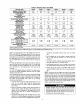

UNIT SIZE 48GX
NOMINAL CAPACITY (ton)
OPERATING WEIGHT (lb.)
COMPRESSORS
Quantity
REFRIGERANT (R-22)
Quantity (lb.)
REFRIGERANT METERING DEVICE
Orifice ID (in.)
CONDENSER COIL
Rows...Fins/in.
Face Area (sq ft)
CONDENSER FAN
Nominal Cfm
Diameter (in,)
Motor Hp (Rpm)
EVAPORATOR COIL
Rows,,.Finslin.
Face Area (sq ft)
EVAPORATOR BLOWER
Nominal Airflow (Cfm)
Size (in.)
Motor Hp (Rpm)
FURNACE SECTION*
Burner Orifice No. (Qty...Drill Size)
Natural Gas
Burner Orifice No. (Qty...Drill Size)
Propane Gas
RETURN-AIR FILTERS (in.)t
Throwaway
• Basedonaltitude of 0 to 2000 ft.
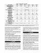
Table 2--Physical Data--Unit 48GX (Continued)
048090 048115 048130 060090
4
421
060115 060130
5 5
468 468
8.3 I 3.1 8.1
.O34
2...17
12.3
33O0
22
¼ (1100)
4...15
4.7
1600
11X 10
3/4 (1075)
3,..38
3..,46
4 4 5
421 421 468
Scroll
1
I 03 I 83 r 81
Acutml Device
.034 .034 ,032
2...17 2...17 2...17
12.3 12.3 16.4
3300 3300 3300
22 22 22
_A(1100) _A(1100) ¼ (1100)
4...15 4...15 4...15
4.7 4.7 4.7
1600 1600 1750
11X10 11X10 11X10
3/4 (1075) 3/4 (1076) 1,0 (1075)
3...33 3,,.31 3.-38
3...42 3...41 3...46
24X30 24X30 24X3024 X 30
.032
2-.17
16,4
3300
22
1A (1100)
' 4...15
4.7
1750
11X 10
1.0 (1075)
3.,.33
3...42
24 X 30
.O32
2...17
16.4
3300
22
(1100)
4...15
4.7
1750
11 X 10
1.0 (1075)
3...31
3,,.41
24 X 30
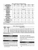
_"Required filter sizes shown are based on the larger of the ARI (Air Conditioningand Refrigeration Institute) rated cooling airflow or the heating airflow velocity of 300
if/minute for high-capacity type. Air tilter pressure drop for non-standard filters must not exceed 0.08 in. wg.
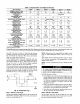
Table 3_Maximum Gas Flow Capacity*
NOMINAL
IRON PIPE,
SIZE
(IN.)
½
¾
1
11A
11A
INTERNAL LENGTH OF PIPE, FTt
DIAMETER
(IN.) 10 20 30 40 50 60 70 80 90 100 126 150
.622 175 120 97 82 73 66 61 57 53 50 44 40
,824 360 250 200 170 151 138 125 118 110 103 93 I 84 77
1.049 680 465 375 320 285 260 240 220 205 195 175 i 160 145
i
1.380 1400 950 770 600 580 530 490 460 430 400 360 I 325 300
1,610 2100 1460 1180 990 900 810 750 690 650 620 550 i 500 460
__apacity_fpipeincu__fgasperhrf_rgaspressure_f__5psig_r_ess_Pressuredr_p____5-in_wg basedona0.60speci cg a',,itygas) Ree oTabeC_l
Fire Protection Association NFPA 54.
f This length includes an ordinary number of fittings.
175 200
72
135
230
430
National
casing.
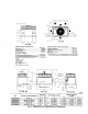
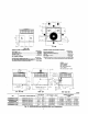
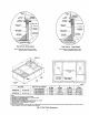
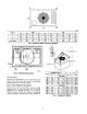
Step 9--INSTALL DUCT CONNECTIONS
The unit has duct flanges on the supply- and return-air openings on
the side and bottom of the unit. For downshot applications, the
ductwork connects to the roof curb (See Fig. 2 and 3 for
connections sizes and locations).
CONFIGURING UNITS FOR DOWNFLOW (VERTICAL) DIS-
CHARGE
serious injury or death.
8. Check for gas leaks at the field-installed and factory-installed
gas lines after all piping connections have been completed.
Use soap-and-water solution (or method specified by local
codes and/or regulations).
10
cause serious injury or death.
1. Open all electrical disconnects before starting any service
work.