
Operating instructions

Untrained personnel can perform basic maintenance functions of
cleaning coils and filters. All other operations should be performed
by trained service personnel. When working on air-conditioning
equipment, observe precautions in the literature, tags, and labels
attached to the unit, and other safety precautions that may apply.
Follow all safety codes. Wear safety gla.gses and work gloves. Use
quenching cloth for unbrazing operations. Have fire extinguisher
available for all brazing operations.
Improper installation, adjustment, alteration, service, mainte-
nance, or u_ can cause carbon monoxide poisoning, fire, or
an explosion which can result in personal injury or unit
damage. Consult a qualified installer, service agency, or gas
supplier for information or assistance. The qualified installer
or agency must use only factory-authorized kits or accessories
when modifying this product.
Before performing service or maintenance operations on unit,
turn off gas supply to unit. Then turn off unit main power
switch and install lockout tag. Electrical shock or explosion
could cause serious injury or death.
Recognize safety information. This is the safety-alert symbolzf x .
When you see this symbol in instructions or manuals, be alert to
the potential for personal injury.
Understand the signal words DANGER, WARNING, CAUTION,
and NOTE. These words are used with the safety-alert symbol.
DANGER identifies the most serious hazards which will result in
serious injury or death. WARNING signifies a hazard which could
result in serious injury or death. CAUTION is used to identify
unsafe practices which would result in minor personal injury or
product and property damage. NOTE is used to highlight sugges-
tions which will result in enhanced installation, reliability, or
operation.
These instructions cover minimum requirements and conform to
existing national standards and safety codes. In some instances,
these instructions exceed certain local codes and ordinances,
especially those that may not have kept up with changing residen-
tial construction practices. We require these instructions as a
minimum for a safe installation.
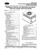
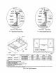
INTRODUCTION
The 48GS and 48GX units (See Fig. 1) are fully self-contained,
combination Category I gas heating/electric cooling units designec[
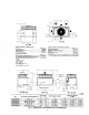
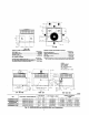
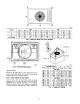
for outdoor installation (See Fig. 2 and 3 for unit dimensions). All
unit sizes have return and discharge openings for both horizontal
and downffuw configurations, and are factory shipped with all
downflow duct openings covered. Units may be installed either on
a rooftop, a cement slab, or directly on the ground if local codes
permit (See Fig. 4 for roof curb dimensions).
Models with an N in the fifth position of the model number are
dedicated Low NO x units designed for California installation.
These models meet the California maximum oxides of nitrogen
(NO,) emissions requirements of 40 nanograms/joule or less as
shipped from the factory and must be installed in California Air
Quality Management Districts where a Low NO_ rule exists.
RECEIVING AND INSTALLATION
Step I_HECK EQUIPMENT
IDENTIFY UN1T
The unit model number and serial number are stamped on unit
identification plate. Check this information against shipping papers
and job data. Verify unit voltage and amperage requirements listed
on unit rating plate agree with power supply provided to unit.
INSPECT SIUPMENT
Inspect for shipping damage while unit is still on shipping pallet.
If unit appears to be damaged or is torn loose from its anchorage,
have it examined by transportation inspectors before removal.
Forward claim papers directly to transportation company. Manu-
facturer is not responsible for any damage incurred in transit.
Check all items against shipping list. Immediately notify the
nearest distributor if any item is missing.
To prevent loss or damage, leave all parts in original packages
until installation.
INSTALLATION
1. Remove unit from shipping carton. Leave top shipping skid on
the unit as a spreader bar to prevent the rigging straps from
damaging the unit. If the wood skid is not available, use a
spreader bar of sufficient length to protect unit from damage.
2. Position the lifting bracket assembly around the base of the
unit. Be sure the strap does not twist.
3. Place each of the 4 metal lifting brackets into the rigging holds
in the composite pan.
4. Thread lifting bracket strapping around bottom perimeter of
unit as follows:
a. Open lever of tension buckle (ratchet type).
b. Feed strapping through tension buckle as shown in Fig. 7.
c. Pull strapping through tension buckle unit taut.
d. Snap lever down to lock strap in tension buckle. To relea._e
strapping, squeeze safety latch, lift lever, and pull webbing
outward.
5. Tighten the tension buckle until it is taut. Lifting brackets
must be secure in the rigging holds.
6. Attach field-supplied clevis or hook of sufficient strength to
hole in the lifting bracket (See Fig. 7).
7. Attach the 2 safety straps directly to the clevis or hook at the
4 rigging brackets. DO NOT attach the safety straps to the
lifting brackets (See Fig. 7).
8. Position lifting point directly over the unit's center of gravity.
9. Lift unit. When unit is directly over the roof curb, remove the
2 safety straps. Lower the equipment onto the roof curb.
Step 2--PROVIDE UNIT SUPPORT
ROOF CURB
Install accessory roof curb in accordance with instructions shipped
with curb (See Fig. 4 for roof curb dimensions). Install insulation,
cant strips, roofing, and flashing. Ductwork must be attached to
curb.
IMPORTANT: The ga,sketing of the unit to the roof curb is critical
for a watertight seal. Install ga.sheting material supplied with the
roof curb. Improperly applied gasketing can also result in air leaks
and poor unit performance.
Curb should be level to within I/4 in. This is necessary for unit
drain to function properly. Refer to accessory roof curb installation
instructions for additional information as required.
SLAB MOUNT
Place the unit on a solid, level concrete pad that is a minimum of
4 in. thick with 2 in. above grade. The slab should be flush on the
compressor end of the unit (to allow condensate drain installation)
and .should extend 2 in. on the three remaining sides of the unit
(See Fig. 6). Do not secure the unit to the slab except when
required by local codes.