
Operating instructions
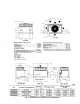

Y
4
2
x 3
COO070
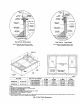
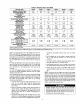
48GS 48GX
CORNER #
030 036 042 048 060 030 036 042 048 060
1 53.2 59.7 67.5 78.9 85.5 59.5 61.O 72.6 80.0 88.9
2 50.4 56.5 63,9 74.7 81,0 56,3 57.8 68.8 75,8 84.2
3 86.8 97.3 110.1 128.7 139.5 97.0 99,5 118.4 130.5 145.1
4 89.6 106.5 113.6 132.8 144.0 100.2 102,7 122.2 134.7 149.8
TOTAL WEIGHT 250 320 355 415 450 313 321 382 421 465
Fig. 5_48GS and 48GX Unit Corner Weights
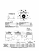
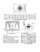
DETAIL A
SEE DETAIL AJ
J
J MINIMUMHEIGHT: _"
C99014
EVAR COND.
COIL COIL
Fig. 6_Slab Mounting Details
GROUND MOUNT
The unit may be installed either on a slab or placed directly on the
ground if local codes permit. Place the unit on level ground
prepared with gravel for condensate di_harge.
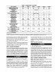
Step 3---FIELD FABRICATE DUC'FWORK
SIZE
I""X'MU 'WE'k HTI 'n l in
UNIT 48GS
A05179
mrn
Secure all ducts to roof curb and building structure on vertical
discharge units. Do not connect ductwork to uniL For horizontal
applications, unit is provided with flanges on the horizontal
openings. Installation of flexible duct connector is recommended
to prevent transmission of vibration and/or noise to structure. All
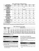
Fig, 7--Suggested Rigging
030 302 137.3 21.5 546.1 13,75 349.3
036 342 155.1 22.5 571.5 14,0 355.6
042 377 171.4 21.5 546.1 13.5 342.9
048 437 198.6 22.0 556.5 17.0 432.0
060 472 214.5 22.0 558,5 17.0 432.0
UNIT 48GX
030 335 152 22.0 558.5 15.30 388.6
036 343 156 22.0 558.5 16.30 388.6
042 404 183 23.0 584,2 16.3 414,0
048 443 201 21.5 546.1 16.3 414.0
060 490 222 23.5 596.9 16.3 414.3