
Operating instructions

UNIT SIZE 48GS
NOMINAL CAPACITY (ton)
OPERATING WEIGHT (lb.)
COMPRESSORS
Quantity
REFRIGERANT (R-22)
Quantity (lb.)
REFRIGERANT METERING DEVICE
Orifice ID (in.)
CONDENSER COIL
Rows...Fins/in.
Face Area (sq ft)
CONDENSER FAN
Nominal Clm
Diameter (in.)
Motor Hp (Rpm)
EVAPORATOR COIL
Rows...Fins/in.
Face Area ($q ft)
EVAPORATOR BLOWER
Nominal Airflow (C/m)
Size (in.)
Motor HP (Rpm)
FURNACE SECTION*
Burner Orifice No. (Qty...Orill Size)
Natural Gas
Burner Orifice No. (Qty.-Drill Size)
Propane Gas
RETURN-AIR FILTERS (in.)t
Throwaway
• Basedonaltitudeof 0 to 2000 It.
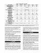
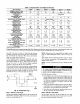
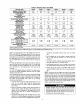
Table 1--Physical Data--Unit 48GS
030040 030060 042060
2½ 2½ 3½
280 280 355
042090
31/2
355
3.65 3,65 5.7 I 5.7
.034
1...17
9.1
2400
22
1/8 (625)
2...15
3.1
1000
10 x 10
1/4(1075)
2...45
2...50
.O34
1...17
9.1
2400
22
1/8 (825)
2._15
3.1
1000
10 x 10
1/4 (1075)
2...38
2-.46
20 X 20
036060 036690
3 3
320 320
Reciprocating
1
I 4.4 4.4
Acutrol TM Device
.032 ,032
1...17 1...17
10.9 10.9
3000 3000
22 22
_A(1100) ,_i (1100)
3._15 3...15
3.1 3.1
1200 1200
11 x 10 11 x 10
1/2 (1075) 1/2 (1075)
2...38 3_,38
2...46 3...46
20 X 24 20 X 24
.O34
1...17
9.1
3000
22
_A (1100)
4...15
3.1
1400
11 x 10
3/4 (1076)
2...3_
2...46
20 x 24
20 x 20
.O34
1...17
9.1
3000
22
(11oo)
4...15
3.1
1400
11 x 10
3/4 (1075)
3...38
3...46
20 X 24
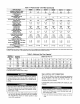
i" Required filtersizes shown are based on the larger of the AR] (Air Conditioning and Refrigeration Institute) rated cooling airflow or the heating ain'low velocity of 300
if]minute for throwaway type or 450 ft]rninute for high-capacity type. Air filter pressure drop for non-standard filters must not exceed 0.08 in. wg.
ductwork should be secured to the flanges. Insulate and weather-
proof all external ductwork, joints, and roof openings with counter
flashing and mastic in accordance with applicable codes.
Ducts passing through an unconditioned space must be insulated
and covered with a vapor barrier.
If a plenum return is used on a vertical unit, the return should be
ducted through the roof deck to comply with applicable fire codes.
A minimum clearance is not required around ductwork. Cabinet
return-air static shall not exceed -.25 in. wg.
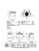
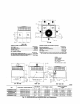
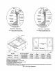
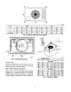
Step 4--PROVIDE CLEARANCES
The required minimum operating and service clearances are shown
in Fig. 2 and 3. Adequate combustion, ventilation and condenser
air must be provided in accordance with section 5.3, Air for
Combustion and Ventilation, of the National Fuel Gas Code ANSI
(American National Standards Institute) Z223.1 or applicable
provisions of local building code. In Canada, follow sections 7.2,
7.3, or 7.4 or Can/CGA. (Canadian Gas Association) B149
Installation Codes or applicable provisions of local building code.
compressor life.
The condenser fan pulls air through the condenser coil and
discharges it through the top cover. Be sure that the fan discharge
does not recirculate to the condenser coll. Do not locate the unit in
either a corner or under an overhead obstruction. The minimum
clearance under a partial overhang (such as a normal house
overhang) is 48-in. above the unit top. The maximum horizontal
extension of a partial overhang must not exceed 48-in..
Do not place the unit where water, ice, or snow from an overhang
or roof will damage or flood the unit. Do not install die unit on
carpeting, tile, or other combustible materialS. The unit may be
installed on wood flooring or on Class A, B, or C roof covering
materials.
Step 5--RIG AND PLACE UNIT
support the additional weight.
Use spreader bars or crate top when rigging the unit. The units
must be rigged for lifting (See Fig. 6). Refer to Table 1 and 2 for
operating weight. Use extreme caution to prevent damage when
moving the unit. Unit must remain in an upright position during all
rigging and moving operatiottv.The unit must be level within 1/4"'
for proper condensate drainage; therefore, the ground-level pad or
accessory roof curb must be level before setting die unit in place.
When a field-fabricated support is used, be sure that the support is
level and properly supports die unit. Lifting point should be
directly over the center of gravity for the unit.
Step 6--CONNECT CONDENSATE DRAIN
NOTE: When installing condensate drain connection be sure to
comply with local codes and restrictions.
Models 48GS and 48GX dispose of condensate water through a
3/4 in. NPT fitting which exits through the compressor access
panel (See Fig. 2 and 3 for location).
Condensate water can be drained directly onto the roof in rooftop
installations (where permitted) or onto a gravel apron in ground-
level installations. Install a field-supplied condensate trap at end of
condensate connection to ensure proper drainage. Make sure that