
Operating instructions

UNIT SIZE 48GS
NOMINAL CAPACITY (ton)
OPERATING WEIGHT (lb.)
COMPRESSORS
Quantity
REFRIGERANT (R-22)
Quantity (lb.)
REFRIGERANT METERING DEVICE
Orifice ID (in.)
CONDENSER COIL
Rows.- Fins/in.
Face Area (sq ft)
CONDENSER FAN
Nominal Cfm
Diameter (in.)
Motor Hp (Rpm)
EVAPORATOR COIL
Rows._Fins/in.
Face Area (sq It)
EVAPORATOR BLOWER
Nominal Airflow (Cfm)
Size (in.)
Motor Hp (Rpm)
FURNACE SECTION*
Burner Orifice No. (Qty._Drill Size)
Natural Gas
Burner Orifice No. (Qty...Drill Size)
Propane Gas
RETURN-AIR FILTERS (in.)t
Throwaway
* Basedon altitudeof0 to 2000 ft.
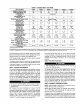
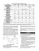
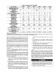
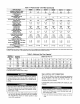
Table 1--Physical Data--Unit 48GS (Continued)
048090 048115 048130 060090
4 4 4 5
415
6.0
.O32
1...17
12,3
3600
22
1A(11o0)
3...15
4.7
1600
11 x lO
3/4 (1075)
3...38
3.,.46
24X30
415 415 450
Scroll
1
I 6.0 ! 6.0 8.0
Acutrol Device
.032 .032 ,030
1,,,17 1..,17 2...17
12.3 12.3 12.3
3600 3600 3600
22 22 22
!4 (1100) 1,4(1100) 1,4(1100)
3...15 3...15 4...15
4.7 4.7 4.7
1600 1600 2000
11X10 11X10 11X10
314 (1075) 3/4 (1075) 1.0 (1075)
3.-33 3...31 3...38
3...42 3...41 3...46
24X30 24X30 24X30
060115 060130
5 5
450 450
Reciprocating
1
I g° I 60
,030
2-,17
12.3
3600
22
1,4(1100)
4...15
4.7
2000
11 X 10
1.0 (1075)
3,,,33
3...42
24 X 30
.030
2...17
12.3
36OO
22
t4 (110o)
4...15
4.7
2000
11 X 10
1.0(1075)
3...31
3...41
24 X 30
t Required filter sizes shown are based on the larger of the ARI Air Conditioning and Refrigeration Institute) rated cooling airflow or the hea ing a rf ow ve oclty o 300
Wrn nste or throwaway type or 450 if/minute for high-capacity type. Air filter pressure drop for non-standard filters must not exceed 0.08 in. wg,
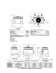
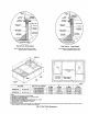
the oudet of the trap is at least 1 in. lower than the drain pan
condensate connection to prevent the pan from overflowing (See
Fig. 8). Prime the trap with water. When using a gravel apron,
make sure it slopes away from the unit.
If the installation requires draining the condensate water away
from the unit, install a 2-in. trap at the condensate connection to
ensure proper drainage (See Fig. 8). Make sure that the outlet of
the trap is at hi&st 1 in. lower than the drainpan condensate
connection. This prevents the pan from overflowing.
Prime the trap with water. Connect a drain tube -using a minimum
of 3/4-in. PVC or 314-in. copper pipe (all field-supplied) - at the
outlet end of the 2-in. trap. Do not undersize the tube. Pitch the
drain tube downward at a slope of at least 1-in. for every 10 R of
horizontal run. Be sure to check the drain tube for leaks.
i q
Fig. 8--Condensate Trap
TRAP
OUTLET
2" rain.
t
C00009
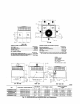
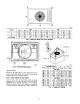
Step 7--INSTALL FLUE HOOD
The flue hood assembly is shipped screwed to the coil panel in the
indoor blower compartment. Remove the service access panel to
locate the assembly (See Fig. 27).
NOTE: Dedicated low NO_ models MUST be installed in Cali-
fornia Air quahty Management Districts where a Low NO_ rule
exists.
These models meet the California maximum oxides of nitrogen
(NO,) emissions requirements of 40 nanograms/joule or less as
shipped from the factory.
NOTE: Low NO. requirements ap-ply only to natural gas instal-
lations.
Install the flue hood as follows:
1. This ir_tallation must conform with local building codes and
with the National Fuel Gas Code (NFGC), ANSI Z223.1 (in
Canada, CAN/CGA B149.1, and B149.2) or NFPA (National
Fire Protection Association) latest revision. Refer to Provin-
cial and local plumbing or wastewa_r codes and other
applicable local codes.
2. Remove flue hood from shipping location (inside the blower
compartment). Place vent cap assembly over flue panel. Orient
screw holes in vent cap with holes in the flue panel.
3. Secure flue hood to flue panel by inserting a single screw on
the right side and the left side of the hood.
Step 8---INSTALL GAS PIPING
The gas supply pipe enters the unit through the access hole
provided. The gas connection to the unit is made to the 1/2-in. FPT
gas inlet on the manual shutoff or gas valve.