
Operating instructions
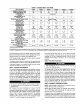
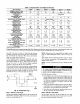
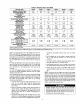

Table 2--Physical Data--Unit 48GX
UNIT SIZE 48GX
NOMINAL CAPACITY (ton)
OPERATING WEIGHT (lb.)
COMPRESSORS
Quantity
REFRIGERANT (R-22)
Quantity (lb.)
REFRIGERANT METERING DEVICE
Orifice ID (in.)
CONDENSER COIL
Rows.-Fins/in.
Face Area (sq ft)
CONDENSER FAN
Nominal Ctm
Diameter (in.)
Motor Hp (Rpm)
EVAPORATOR COIL
Rows...Fins/in.
Face Area (sq ft)
EVAPORATOR BLOWER
Nominal Airflow (Cfm)
Size (in.)
Motor Hp (Rpm)
FURNACE SECTION*
Burner Orifice No. (Qty.-Drill Size)
Natural Gas
Burner Orifice No. (Qty...Dri0 Size)
Propane Gas
RETURN-AIR FILTERS (in.)t
Throwaway
• Based on altitude of 0 to2000 ft.
030040
2½
313
030060
2½
313
036060
3
321
_6060
3
_roll
1
042060 042090
3½ 3½
382 382
4.4 4.4 5.2 5.2 6.4 6.4
.030 .030 .032 .032 .034 .034
1...17 1...17 2...17 2...17 2...17 2...17
12.7 12.7 9.1 9.1 12.3 12.3
2350 2350 2350 2350 3300 3300
22 22 22 22 22 22
1/8 (825) 1/8 (825) 1/8 (825) 1/8 (825) 1/8 (825) 1/8 (825)
3...15 3...15 3...15 3...15 3...15 3...15
3.1 3.1 3.7 3.7 4.7 4.7
1006
lOX10
1/4 (1075)
2...38
2...46
20 X 20
106O
10x10
1/4 (1075)
1200
11 X 10
1/2 (1075)
2,,,38
2...46
20 X 24
2...44
2,,.50
1200
11X10
1/2 (1075)
3,,,38
3,,,46
20 X 2420 X 20
1400
11X 10
3/4 (1075)
2..,38
2..,46
24 X 30
1400
11X 10
3/4 (1075)
3...38
3...46
24 X 30
f Required filter sizes shown are based on the larger of the ARI (Air Conditioning and Refrigeration Institute) rated cooling airflow or the heating airflow velocityof 300
if]minute for high-capacity type. Air riser pressure drop for non-standard filters must not exceed 0.08 in. wg.
Install a gas supply line that runs to the heating section. Refer to
Table 3 and the NFGC for gas pipe sizing. Do not use cast-iron
pipe. It is recommended that a black iron pipe is used. Check the
local utility for recommendations concerning existing tines. Size
gas supply piping for 0.5 in. wg maximum pressure drop. Never
use pipe smaller than the 1/2-in. FPT gas ial_'t on the unit gas
valve.
For natural gas applications, the gas pressure at unit gas connection
must not be less than 4.0 in. wg or greater than 13 in. wg while the
unit is operating. For propane applications, the gas pressure must
not be less than 7.0 in. wg or greater than 13 in. wg at the unit
connection.
An l/8-in. NPT plugged tapping, accessible for test gage connec-
tion, must be installed immediately upstream of the gas supply
connection to the gas valve.
When installing the gas supply fine, observe local codes pertaining
to gas pipe installations. Refer to the NFGC ANSI Z223.1-1988
NFPA latest edition (in Canada, CAN/CGA B149.1, (2)-M86). In
the absence of local building codes, adhere to the following
pertinent recommendations:
1. Avoid low spots in long runs of pipe. Grade all pipe 1/4 in. in
every 15 ft to prevent traps. Grade all horizontal runs
downward to risers. Use risers to connect to heating section
and to meter.
2. Protect all segments of piping system against physical and
thermal damage. Support all piping with appropriate straps,
bangers, etc. Use a minimum of one hanger every 6 ft. For
pipe sizes larger than l/2 in., follow recommendations of
national codes.
3. Apply joint compound (pipe dope) sparingly and only to male
threads of jc;mt when making pipe connections. Use only pipe
dope that is resistant to action of liquefied petroleum gases as
4.
specified by local and/or national codes. Never use Teflon
tape.
Install sediment trap in riser leading to heating _ction (See
Fig. 9). This drip leg functions a.s a trap for dirt and
condensate.
5. Install an accessible, external, manual main shutoff valve in
gas supply pipe within 6 ft of heating section.
6. Install ground-joint union close to heating section between
unit manual shutoff and external manual main shut-off valve.
7. Pressure-test all gas piping in accordance with local and
national plumbing and gas codes before connecting piping to
unit.
NOTE: Pressure test the gas supply system after the gas supply
piping is connected to the gas valve. The supply piping must be
disconnected from the gas valve during the testing of the piping
systero_s when test pressure is in excess of 0.5 palg. Pressure test
the gas supply piping system at pressures equal to or less than 0.5
psig. The unit heating section must be isolated from the gas piping
system by closing the external main manual shutoff valve and
slightly opening the ground-joint union.
Wl E_
Unstable operation may occur when the gas valve and
manifold assembly are forced out of position while connect-
ing improperly-routed rigid ga_s piping to the gas valve. Use
a backup wrench when making connection to avoid strain on,
or distortion of, the ga._ control piping.