
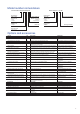
Specifications


12
Water-cooled packaged liquid chiller for indoor installation,
equipped with numerical control, and operating with
chlorine-free refrigerant HFC-134a.
■ Regulations
The unit characteristics must be published in accordance
with ARI standards.
The machines with CE marking must comply with the
following European directives:
- Pressurised equipment directive (PED) 97/23/EC
- Machinery directive 2004/108/EEC, modified
- Low voltage directive 2006/90/EC, modified
- Electromagnetic compatibility directive 2004/108/EEC,
modified
- Machine safety: electrical equipment in machines,
general regulations, EN 60204-1
- Electromagnetic immunity, industrial levels: EN61000-6-4
for 19XR machines, and EN61800-3, second installation
environment for 19XRV machines.
- Electromagnetic emission, industrial levels: EN61000-6-2
for 19XR machines and 61800-3 for 19XRV machines.
■ Quality■assurance
- The unit shall be designed, manufactured and tested at a
facility with a quality assurance system certified ISO 9001.
- The unit shall be manufactured at a facility with a
environment management system certified ISO 14001.
- The unit must satisfy the quality control tests in the
factory (pressure and electrical tests).
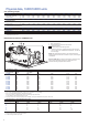
■ One high-performance, single-stage centrifugal hermetic
compressor. Connections to the compressor casing use
O-rings instead of gaskets to reduce the occurrance of
refrigerant leakage.
■ The open type impeller with machined shroud contours
and impeller diameter optimise compressor efficiency for
each specified application.
■ Tubing is copper, high-efficiency type, with integral internal
and external enhancement. Tubes are nominal 3/4-in. OD
with nominal wall thickness of 0.635 mm measured at the
root of the fin. Tubes are rolled into tube sheets and are
individually replaceable. Tube sheet holes are double
grooved for joint structural integrity. Intermediate support
sheet spacing does not exceed 914 mm.
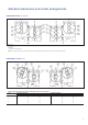
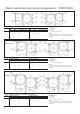
■ Waterboxes and nozzle connections are designed for 1034
kPa maximum working pressure unless otherwise noted.
Nozzles have grooves to allow use of Victaulic couplings.
■ The tube sheets of the cooler and condenser are bolted
together to allow for field disassembly and reassembly.
■ Waterboxes have vents, drains, and covers to permit tube
cleaning within the space shown on the drawings. A
thermistor type temperature sensor is factory installed in
each water nozzle.
■ The heat exchangers display a European code nameplate
which shows the pressure-temperature data. A pressure
relief valve is installed on each heat exchanger. A pressure
relief valve device is installed on each heat exchanger
which permits verification of the set point without transfer
of the charge.
■ Cooler is designed to prevent liquid refrigerant from
entering the compressor.
■ Tubes are individually replaceable from either end of the
heat exchanger without affecting the strength and durability
of the tube sheet and without causing leakage in adjacent
tubes.
■ The condenser shell includes a FLASC (flash subcooler)
which cools the condensed liquid refrigerant to a reduced
temperature, thereby increasing the refrigeration cycle
efficiency.
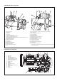
Galvanized sheet steel, polyester paint finish, colour light
grey, with hinged access doors, containing:
- The variable-frequency drive/starter with the unit dis-
connect device and the short-circuit protections (standard
for 19XRV machines and optional for 19XR machines)
- The heater and oil pump control and power supply
equipment.
- The automated electronic control devices including the
ICVC interface and the electronic input/output boards.
■ Set■point■functions
The control provides the capability to view and change the
leaving chilled water set point, entering chilled water set
point, and demand limit set point at any time during chiller
operating or shutdown periods. The controls allow for the
specification of capacity control by either leaving chilled
water or entering chilled water.
■ Service■function
The control provides a password protected service
function which allows authorized individuals to:
- View an alarm history file which contains the last 25
alarm/alert messages with time and date stamp. These
messages are displayed in text form, not codes.
- Execute a chiller controls test function for quick
identification of malfunctioning components
- View/modify chiller configuration
- View/modify chiller occupancy periods
- View/modify schedule holiday periods
- View/modify schedule override periods
- View/modify system time and date
■ Lead/lag■function
Lead/lag function automatically controls two chillers,
including the reversing sequence. A third chiller can be
added to the lead lag system as a standby chiller.
■ Communication
Interface with other CCN devices is available as standard.
A CCN/JBus (Carrier Comfort Network) interface
facilitates communication with other BMS systems.