
User's Manual
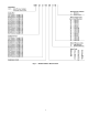
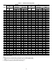

COMPRESSOR
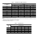
FRAME SIZE*
COOLER
SIZE
MAXIMUM
WEIGHT (lb)
VESSEL
LENGTH
DIM. ‘‘A’’ DIM. ‘‘B’’ DIM. ‘‘C’’
CHAIN LENGTH
‘‘D’’ ‘‘E’’ ‘‘F’’
4
70-72 40,410 148 68-69 38-49 38-59 118-69 128-59 128-99
75-77 44,210 168 78-59 38-59 38-59 128-09 138-39 138-69
5
70-72 45,600 148 68-29 38-69 38-79 118-69 128-59 128-99
75-77 49,400 168 68-119 38-69 38-69 128-09 138-39 138-69
80-82 54,900 148 68-29 38-69 38-79 118-69 128-59 128-99
85-87 58,300 168 68-119 38-69 38-69 128-09 138-39 138-69
*The first digit of the 3-digit compressor code indicates the frame size of the compressor.
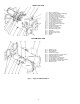
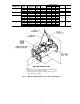
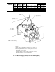
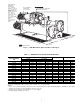
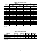
MACHINE RIGGING GUIDE
NOTES:
1. Each chain must be capable of supporting the entire weight of the
machine. See chart for maximum weights.
2. Chain lengths shown are typical for 158 lifting height. Some minor
adjustments may be required.
3. Dimensions ‘‘A’’ and ‘‘B’’ define distance from machine center of
gravity to tube sheet outermost surfaces. Dimension ‘‘C’’ defines
distance from machine center of gravity to floor.
Fig. 4 — Machine Rigging Guide (Cooler Size 70 Through 87)
CG — Center of Gravity
6