Product Data 23XL Hermetic Screw Liquid Chiller 50/60 Hz 60 Hz — 150 to 360 Nominal Tons (530 to 1,270 kW) 50 Hz — 130 to 300 Nominal Tons (460 to 1,060 kW) The 23XL screw chiller provides the performance and reliability of a centrifugal class machine by using advanced engineering technology. Optimized for low life cycle costs, the 23XL offers superior value in a compact design.
Variable refrigerant metering eliminates inefficient vapor bypass and provides superior part-load performance when compared to fixed orifice metering designs. High efficiency hermetic motors, cooled by liquid refrigerant, reduce motor electrical losses. Low installation costs A positive pressure design reduces the size of the chiller by as much as 35% when compared to negative pressure designs. The reduced machine size results in lower floor space requirements and easier installation.
Features/Benefits (cont) Automatic two chiller lead/lag capability provides integral standby controls. A 16 line by 40 character LCD display offers ‘‘all in one glance’’ access to key chiller operating information. Local Interface Device (LID) provides unparalled ease of user interface. The LCD display features 4 menu specific softkeys and a simple, intuitive design. Modular pull-out/plug-in design requires minimal wiring and simplifies installation. Low voltage design is safe and reliable.
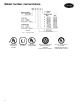
Model number nomenclature LEGEND VI — Volumetric Index Underwriters’ Laboratory Canada 4 ASME ‘U‘ Stamp Underwriters’ Laboratories ARI (Air Conditioning and Refrigeration Institute) Performance Certified Carrier Corporation, TR-1 Plant Registered to ISO 9001 Certificate No.
Features/Benefits (cont) 23XL HERMETIC SCREW LIQUID CHILLER (FRAME 1 AND 2 CHILLERS) Technologically advanced chillers designed to answer today’s environmental and energy-efficiency concerns • Compact positive pressure design provides migration path to HFC’s • Low sound levels for the most demanding acoustic applications • Variable refrigerant metering for superior part-load performance • High efficiency design optimized for air-conditioning/light brine duty • Comprehensive factory testing program MICROPROC
Feature/Benefits (cont) 23XL HERMETIC SCREW LIQUID CHILLER (FRAME 4 CHILLERS) Technologically advanced chillers designed to answer today’s environmental and energy-efficiency concerns • Compact positive pressure design provides migration path to HFC’s • Low sound levels for the most demanding acoustic applications • Variable refrigerant metering for superior part-load performance • High efficiency design optimized for air-conditioning/light brine duty • Comprehensive factory testing program MICROPROCESSOR C
23XL Refrigeration Cycle The compressor continuously draws refrigerant vapor from the cooler at a rate determined by the position of the capacity control slide valve. This compressor suction reduces the pressure in the cooler and causes the remaining refrigerant to boil vigorously at a low temperature (typically 38 to 42 F [3 to 6 C]). The energy required for boiling is obtained as heat from the water (or brine) flowing through the cooler tubes.
Features/Benefits (cont) TYPICAL 23XL REFRIGERATION CYCLE ECONOMIZED CHILLERS TYPICAL 23XL REFRIGERATION CYCLE NON-ECONOMIZED CHILLERS 8
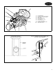
SCREW COMPRESSOR COMPONENTS 1 2 3 4 5 6 7 8 9 10 TAKE-APART DESIGN SIMPLIFIES INSTALLATION — — — — — — — — — — Control Oil Lines Capacity Control Solenoid Valve Discharge Bearing Assemblies Male Rotor Semi-Hermetic Motor Female Rotor Rotor Oil Injection Port Suction Inlet Flange Capacity Control Slide Valve Slide Piston Seals TYPICAL RABBET-FIT BOLT CONNECTOR FOR EASY REALIGNMENT 9
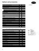
Options and accessories ITEM Shipped Factory Charged with Refrigerant Shipped Factory Charged with Nitrogen One, 2, or 3 Pass Cooler or Condenser Waterside Construction Full Insulation (except waterbox covers) Refrigerant Isolation Package Waterbox Options (Frame 4 Machines Only): 300 psig (2068 kPa) Nozzle-in-Head Waterboxes 300 psig (2068 kPa) Marine Waterboxes 300 psig Flanged Cooler and/or Condenser Waterbox Nozzles Automatic Electric Hot Gas Bypass Unit-Mounted Wye-Delta or Solid-State Low Voltage Star
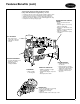
Machine components FRONT VIEW 1 — Power Panel 2 — Local Interface Display (LID) Control Center 3 — ASME (American Society of Mechanical Engineers) Nameplate, Cooler 4 — Cooler Refrigerant Isolation Valve 5 — ASME Nameplate, Economizer (Hidden) 6 — Service Valve 7 — Take-Apart Rabbet Fit Connector (Lower) 8 — Cooler Temperature Sensor 9 — ASME Nameplate, Condenser 10 — Typical Waterbox Drain Port 11 — Cooler Supply/Return End Waterbox Cover 12 — Condenser Supply/Return End Waterbox Cover 13 — Compressor Nam
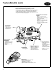
Machine components (cont) FRONT VIEW 1 2 3 4 — — — — 5 — 6 — 7 — 8 9 10 11 12 13 14 15 16 17 — — — — — — — — — — 18 19 20 21 22 23 24 25 26 27 28 29 30 31 — — — — — — — — — — — — — — Compressor Nameplate Power Panel Local Interface Display (LID) Control Center ASME (American Society of Mechanical Engineers) Nameplate, Cooler Cooler Vessel Separation Feet Economizer Float Valve Access Cover (Hidden) Refrigerant Charging Valve Economizer Oil Filter Assembly (Hidden) ASME Nameplate, Economizer Typical W
Physical data NOMINAL CAPACITY TONS (kW) 60 Hz 50 Hz Size Frame Size Frame 150 (530) 130 (460) 10,11 1 10,11 1 185 (650) 150 (530) 10,11 1 10,11 200 (700) 165 (580) 10,11 1 230 (810) 190 (670) 20,21 250 (880) 205 (720) 20,21 COOLER CONDENSER ECONOMIZER COMPRESSOR Size VI N C2 0 or 1 1 N C4 0 10,11 1 Y C4 0 or 1 2 20,21 2 N C6 0 2 20,21 2 Y C6 0 or 1 TOTAL TOTAL REFRIGERANT OPERATING UNIT DRY WEIGHT WEIGHT* MOUNTED WEIGHT STARTER lb kg lb kg lb kg Y 9,75
Physical data (cont) COMPRESSOR WEIGHTS 23XL UNIT ASSEMBLY lb kg 2270 1029 2300 1043 2400 1088 3300 1497 3400 1542 COMPRESSOR SIZE C2 C4 C6 D4 D6 Frame 1 Frame 2 Frame 4 COMPONENT WEIGHTS FRAME 1 AND 2 lb kg 1180 535 296 134 170 77 COMPONENT Oil Separator Economizer† Muffler Discharge Piping: Pipe Isolation Valve† Adaptor Flange Power Panel Starter† Control Center 44 30 76 20 500 31 FRAME 4 lb kg 2880* 1306* 560 254 * * 20 14 34 9 227 14 — 30 76 20 500 31 — 14 34 9 227 14 *The Frame 4 muffler is
WATERBOX COVER WEIGHTS (FRAME 1 AND 2 CHILLERS)* HEAT EXCHANGER WATERBOX DESCRIPTION PSI (kPa) Cooler or Condenser NIH, 1 Pass NIH, 2 Pass (Plain) NIH, 2 Pass (With Pipe Nozzles) 150 (1034) NIH, 3 Pass 150 (1034) FRAME 1 FRAME 2 lbs 118 100 185 kg 54 46 84 lbs 128 148 200 kg 58 67 91 166 76 180 82 LEGEND NIH — Nozzle-In-Head *These weights are given for reference only. They have been included in heat exchanger weights shown in the Heat Exchanger Weights table on page 14.
Dimensions 23XL FRAME 1 AND 2 CHILLERS NOTES: 1. Service access should be provided per ANSI/ASHRAE 15 (American National Standards Institute/ American Society of Heating Refrigeration and Air Conditioning Engineers), Latest Edition, NFPA (National Fire Protection Association) 70, and local safety codes. 2. A minimum of 6 in. overload clearance for service rigging is recommended. 3. Certified drawings available upon request. 4. ( ) indicates millimeters.
23XL FRAME 4 CHILLERS NOTES: 1. For flanged waterbox nozzles, refer to the certified drawings for length addition measurements. 2. Service access should be provided based on American Society of Heating, Refrigeration, and Air Conditioning Engineers (ASHRAE) 15, latest edition, National Fire Protection Association (NFPA) 70, and local safety codes. 3. A minimum of 6 in. (152 mm) overhead clearance for service rigging is recommended. 4. Certified drawings are available upon request. 5.
Electrical data COMPRESSOR Size VI Type C2 0 MOTOR ELECTRICAL CHARACTERISTICS RLA per IkW LRA Wye LRA Delta RLA per IkW LRA Wye LRA Delta RLA per IkW LRA Wye LRA Delta RLA per IkW LRA Wye LRA Delta RLA per IkW LRA Wye LRA Delta 0 C4 1 C6 0 or 1 D4, D6 0 or 1 60 Hz MOTORS Low Voltage Max IkW 125 155 195 195 280 208 V 230 V 400 V 460 V 575 V 3.01 789 2465 3.04 1026 3206 2.97 990 3095 2.97 990 3095 3.04 1530 4780 2.86 713 2229 2.95 928 2899 2.73 896 2799 2.73 896 2799 2.74 1325 4139 1.
Performance data Computerized ratings Part-load performance Because of the large number of available Carrier 23XL Screw Chiller component combinations and the wide variability in required operating conditions, it is impractical to provide tabular performance information. Tabulated performance ratings predict ‘‘typical’’ chiller performance. Actual chiller performance may vary significantly at actual operating conditions and as chiller components are optimized around these conditions.
Application data (cont) CHILLER FOOTPRINT (FRAME 1 AND 2 CHILLERS) DIMENSION A B C HEAT EXCHANGER SIZE 10 or 11 20 or 21 ft-in. mm ft-in. mm 4-51⁄4 1353 4-71⁄4 1403 4-41⁄2 1334 4-61⁄2 1384 1-03⁄8 314 1-13⁄8 340 NOTES: 1. Dimensions in ( ) are in millimeters. 2. Use grout and package components to establish the level base line. 3. If chiller is set on concrete pad, electrical contractor must locate conduit stub-ups outside of pad. Approximate location shown. CHILLER FOOTPRINT (FRAME 4 CHILLER) NOTES: 1.
STANDARD ISOLATION VIEW B-B NOTES: 1. Dimensions in ( ) are in millimeters. 2. Isolation package includes 4 shear flex pads. ACCESSORY ISOLATION HRS — Hot Rolled Steel NOTES: 1. Dimensions in ( ) are in millimeters. 2. Accessory (Carrier supplied, field installed) soleplate package includes 4 soleplates, 16 jacking screws and leveling pads. Requires accessory spring vibration isolation package. 3. Jacking screws to be removed after grout has set. 4.
Application data (cont) FRAME 1 AND 2 NOZZLE ARRANGEMENTS COOLER AND CONDENSER NOZZLE ARRANGEMENTS NOZZLE ARRANGEMENT CODES Cooler Pass 1 2 3 In 1 2 3 5 7 9 Out 2 1 4 6 8 10 Code A B C D E F Pass 1 2 3 In 11 12 13 15 17 19 Condenser Out 12 11 14 16 18 20 Code J K L M N P WATERBOX NOZZLE SIZES FRAME 1 2 LEGEND ID — Inside Diameter 22 PASS 1 2 3 1 2 3 NOMINAL PIPE SIZE (in.) Cooler and Condenser 6 6 6 8 6 6 ACTUAL PIPE ID (in.) Cooler and Condenser 6.065 6.065 6.065 7.981 6.065 6.
FRAME 4 NOZZLE ARRANGEMENTS COOLER AND CONDENSER NOZZLE ARRANGEMENTS NOZZLE ARRANGEMENT CODES Cooler Pass 1 2 3 In 8 5 7 4 7 4 Out 5 8 9 6 6 9 Code A B C D E F Pass 1 2 3 In 11 2 10 1 10 1 Condenser Out 2 11 12 3 3 12 Code P Q R S T U WATERBOX NOZZLE SIZES FRAME PASS 4* 1 2 3 NOMINAL PIPE SIZE (in.) Cooler and Condenser 10 8 6 ACTUAL PIPE ID (in.) Cooler and Condenser 10.020 7.981 6.065 *Frame 4 waterboxes are factory fabricated with bolt-on covers.
Application data (cont) Vent and drain connections All vents and drain connections are found in the waterbox covers. Connection size is 3⁄4-in. FPT. Provide high points of the chiller piping system with vents and the low points with drains. If shut-off valves are provided in the main water pipes near the unit, a minimum amount of system water is lost when the heat exchangers are drained. This reduces the time required for drainage and saves on the cost of re-treating the system water.
INSULATION REQUIREMENTS COMPONENT Cooler Compressor Economizer Economized Liquid Lines Non-Economized Liquid Lines FRAME 1 2 4 1, 2 4 1, 2 4 — — FT2 60 66 113 35 41 17 28 21 9 M2 5.57 6.13 10.49 3.25 3.81 1.58 2.60 1.95 .84 Factory insulation (optional) — Optional factory insulation is available for the evaporator shell and tube sheets, suction pipe, motor end of compressor, economizer, and economizer line(s). Insulation applied at the factory is 3⁄4-in. (19.
Application data (cont) INSULATION AREA FOR FRAME 1 AND 2 CHILLERS INSULATION AREA FOR FRAME 4 CHILLERS 26
FLOOR CONTACT SURFACE LOADING HEAT EXCHANGER FRAME 1 2 4 PAD POSITION A B C D A B C D A B C D MINIMUM lb kg 2970 1347 2740 1243 2270 1029 2120 961 3090 1401 3030 1374 2500 1134 2550 1156 4240 1923 4530 2054 4420 2004 4720 2141 MAXIMUM lb kg 3310 1501 3200 1451 2630 1193 2570 1165 3450 1565 3520 1596 2930 1329 3020 1370 5940 2694 6320 2866 6180 2803 6580 2984 FRAME 1 AND 2 CHILLERS FRAME 4 CHILLERS 27
Controls Microprocessor controls Microprocessor controls provide the safety, interlock, capacity control and indications necessary to operate the chiller in a safe and efficient manner. Control system The microprocessor control on each Carrier 23XL screw chiller is factory mounted, wired, and tested to ensure chiller protection and effective capacity control.
MICROPROCESSOR CONTROL CENTER SOFTKEYS 29
Controls (cont) CONTROL CENTER (FRONT VIEW), WITH OPTIONS LEGEND 1 — Local Interface Device (LID) Input/Output Interface Panel Display 2 — Processor Module (PSIO) The PSIO is the brain of the Product Integrated Controls 3 — Optional 8-Input Module for Spare Inputs to Control Interface (One of Two Available) 4 — Power Transformer 5 — 6-Pack Relay Board 6 — Circuit Breakers (4) TYPICAL LOCAL INTERFACE DEVICE (LID) DISPLAY SCREENS Default Display — Displays information most commonly required for chiller ope
TYPICAL LOCAL INTERFACE DEVICE (LID) DISPLAY SCREENS (cont) Schedule Screen — A user established occupancy schedule can be easily configured for your particular application. A 365-day real time, battery backed-up clock will automatically start and stop the chiller according to your established schedule or the building’s master schedule in a CCN system. Set Point Screen — The chilled water, demand limit, and ice build set points can be entered, stored, viewed, or changed easily from this screen.
Controls (cont) TYPICAL LOCAL INTERFACE DEVICE (LID) DISPLAY SCREENS (cont) The Control Test Screen — This screen allows access to the various control tests available to the service technician. The technician can then quickly identify sources of problems and get the chiller back on line.
CONTROL SEQUENCE A — START INITIATED: Pre-start checks are made; chilled water pump started B — Condenser water pump started (5 seconds after A) C — Water flows verified (30 seconds to 5 minutes maximum) D — Chilled water temperature checked against control point; tower fan control enabled; slide valve decrease timer checked to verify slide valve position E — Refrigerant type verified (up to 3 minutes after D).
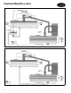
Typical piping and wiring 23XL CHILLER WITH FREE-STANDING STARTER 1 2 3 4 5 6 7 8 9 10 34 — — — — — — — — — — LEGEND Chilled Water Pump Starter Condenser Water Pump Starter Cooling Tower Fan Starter Condenser Water Pump Chilled Water Pump Disconnect Freestanding Compressor Motor Starter Compressor Motor Terminal Box Power Panel (Hidden) Vents Piping Control Wiring Power Wiring NOTES: 1.
23XL CHILLER WITH OPTIONAL UNIT-MOUNTED STARTER 1 2 3 4 5 6 7 — — — — — — — LEGEND Chilled Water Pump Starter Condenser Water Pump Starter Cooling Tower Fan Starter Chilled Water Pump Condenser Water Pump Disconnect Vents Piping Control Wiring Power Wiring NOTES: 1. Wiring and piping shown are for general point-of-connection only and are not intended to show details for a specific installation. Certified field wiring and dimensional diagrams are available on request.
Typical field wiring 23XL TYPICAL FIELD WIRING WITH FREE-STANDING STARTER (FRAME 1 AND 2 CHILLERS) IMPORTANT: Wiring shown is typical and not intended to show detail for a specific installation. Refer to certified field wiring diagrams.
23XL TYPICAL FIELD WIRING WITH FREE-STANDING STARTER (FRAME 1 AND 2 CHILLERS) (cont) LL MCM NEMA NFPA N.O. PR RLA T TB — — — — — — — — — LEGEND Compressor Motor Starter Terminals Thousand Circular Mils National Electrical Manufacturer’s Association National Fire Protection Association Normally Open Pilot Relay Rated Load Amps Terminal Terminal Block Required Power Wiring Required Control Wiring Options Wiring NOTES: I. GENERAL 1.
Typical field wiring (cont) 23XL TYPICAL FIELD WIRING WITH OPTIONAL UNIT-MOUNTED STARTER (FRAME 1 AND 2 CHILLERS) IMPORTANT: Wiring shown is typical and not intended to show the detail for a specific installation. Refer to certified field wiring diagrams.
23XL TYPICAL FIELD WIRING WITH OPTIONAL UNIT-MOUNTED STARTER (FRAME 1 AND 2 CHILLERS) (cont) MCM NEMA N.O. PR RLA ST TB — — — — — — — LEGEND Thousand Circular Mils National Electrical Manufacturer’s Association Normally Open Pilot Relay Rated Load Amps Shunt Trip Terminal Block Required Power Wiring Required Control Wiring Options Wiring NOTES: I. GENERAL 1.0 Starters shall be designed and manufactured in accordance with Carrier Engineering Requirement Z-375. 1.
Guide specifications Packaged Hermetic Screw Liquid Chiller Size Range: 150 to 360 Tons (530 to 1270 kW) — 60 Hz 130 to 300 Tons (460 to 1060 kW) — 50 Hz Carrier Model Number: 23XL Part 1 — General 1.01 SYSTEM DESCRIPTION A. Microprocessor-controlled liquid chiller using a twin rotor, 3550 rpm (60 Hz) or 2960 rpm (50 Hz), direct drive, semi-hermetic, screw compressor using refrigerant HCFC-22 or HFC-134a. Chillers using CFC refrigerants such as CFC-11, CFC-12, or CFC/ HFC-500 shall not be acceptable.
7. Compressor safeties shall include high compressor discharge temperature, high motor winding temperature, low oil pressure, reverse rotation, and high discharge pressure. 8. Compressor shall be equipped with internal pressure relief to protect against overpressure. For compressors not equipped with internal pressure relief, the high side of the chiller shall be protected with an external relief valve capable of passing the full load flow produced by the compressor. 9.
Guide specifications (cont) 2. Tubing shall be copper, high-efficiency type, with integral internal and external enhancement. Tubes shall be nominal 3⁄4-in. OD with standard wall thickness of 0.025 in. measured at the root of the fin. Tubes shall be rolled into tube sheets and shall be individually replaceable. Tube sheet holes shall be double grooved for joint structural integrity. Intermediate support sheet spacing shall not exceed 36 inches. 3.
d. e. f. g. h. i. Upon request to start the compressor, the control system shall start the chilled water pump, condenser water pumps, and tower fans, if appropriate, and verify that flows have been established. The controller shall then compare the entering/leaving chilled water temperature with the chilled water set point.
Guide specifications (cont) one year in advance (month, day, and duration of days). Display of the occupancy schedules shall be viewable on the LCD screen. Each schedule shall provide a means of configuring an occupancy time override to permit a ‘‘one time extension’’ of an occupied period on the configured day. The controls shall also provide for chiller start-up and shutdown through a remote contact closure from a customer supplied device or from a building management system software command.
c. A slide valve test shall energize the increase and decrease slide valve solenoids to check for proper operation. The controls shall request manual operation confirmation of proper solenoid operation before proceeding to the next test. d. In addition to a comprehensive automated Control Test, the controls shall provide a manual option that permits selection and testing of individual control components and inputs.
Guide specifications (cont) J. Insulation: 1. Chilled water piping and cooler waterboxes shall be insulated by the mechanical contractor. 2. Factory installed insulation shall be available for the chiller. Additional insulation shall be installed at the jobsite by the mechanical contractor. 3. Chiller insulation shall be 3⁄4-in. thick and shall have a thermal conductivity not exceeding 0.28 Btu • in./hr • sq ft • F and shall conform to UL Standard 94, Classification 94 HBF. K.
Carrier Corporation • Syracuse, New York 13221 11-96 Manufacturer reserves the right to discontinue, or change at any time, specifications or designs without notice and without incurring obligations. Book 2 Tab 5e Page 48 Catalog No. 522-304 Printed in U.S.A.