
Specifications


Manufacturer reserves the right to discontinue, or change at any time, specifications or designs without notice and without incurring obligations.
PC 903 Catalog No. 533-00001 Printed in U.S.A. Form 30G,H-9SI Pg 1 6-00 Replaces: New
Book 2
Tab 5 c
Installation Instructions
Part Number 30GT-911---062
CONTENTS
SAFETY CONSIDERATIONS
. . . . . . . . . . . . . . . . . . . . . . 1
GENERAL
. . . . . . . . . . . . . . . . . . . . . . . . . . . . . . . . . . . . . . . . 1
INSTALLATION
. . . . . . . . . . . . . . . . . . . . . . . . . . . . . . . . . 1-5
OPERATION
. . . . . . . . . . . . . . . . . . . . . . . . . . . . . . . . . . . . .6,7
CLEANING, SERVICE AND MAINTENANCE
. . . . . . . 7
SAFETY CONSIDERATIONS
Installation of this accessory can be hazardous due to sys-
tem pressures, electrical components, and equipment location
(such as a roof or elevated structure).
Only trained, qualified installers and service technicians
should install, start up, and service this equipment.
When installing this accessory, observe precautions in the
literature, labels attached to the equipment, and any other
safety precautions that apply.
• Follow all safety codes.
• Wear safety glasses and work gloves.
• Use care in handling and installing this accessory.
GENERAL
Check Package Contents —
Check package for
missing parts or shipping damage. If damage is found, or any
part is missing, file a claim with the shipper immediately. The
package contains these instructions, clamp and screw, and the
Navigator module.
The Navigator is a portable display module that conforms to
NEMA 4 specifications for outdoor use in temperatures rang-
ing from –22 F (–30 C) to 158 F (70 C). The Navigator can be
used to configure and perform service diagnostics on machines
equipped with Carrier ComfortLink controls.
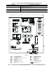
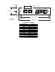
The Navigator keypad (see Fig. 1) contains eleven menu
LED's and one Alarm Status LED, all of which are red. The
Navigator is capable of displaying four 24-character lines of in-
formation on a back-lit liquid crystal display. The Navigator
has four functional keys which are the up arrow ( ), down
arrow ( ), and keys.
INSTALLATION
1. The Navigator display module is intended to be a mobile
device, so there are no holes in the device for permanent
mounting. The module has a magnetic mount that is
strong enough to hold the device in place on any clean,
dry metal surface.
2. The Navigator module is powered through the
ComfortLink Main Base Board (MBB). The Navigator
has a modular telephone style (RJ14) connector and
should be connected to terminal block TB3 in the control
box. This device is intended for use on the LEN (Local
Equipment Network) communications bus only. Do NOT
connect the Navigator to the CCN (Carrier Comfort Net-
work) connector. You may damage the device. Terminal
block TB3 locations are listed in Table 1 on page 2.
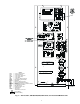
3. Figures 2-4 show TB3 locations in the units. Note that the
LEN connector is clearly marked and is on the right side
of the terminal block. If the Navigator is intended to re-
main with the chiller, secure the cable near TB3 to pre-
vent accidental damage to the RJ14 connector or the TB3
LEN connector. A clamp and screw are provided in the
package for this purpose. An
1
/
8
-in. hole should be drilled
to use the clamp and screw.
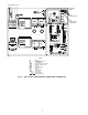
4. Figure 5 shows Communication board details and
dimensions.
ELECTRIC SHOCK HAZARD.
To avoid the possibility of electrical shock,
open and tag all disconnects before install-
ing this equipment.
ENTER ESCAPE
30GTN015-035
30GTN,GTR,GUN,GUR040-420
30HK040-060,30HL050-060,30HW018-040
ComfortLink™ Navigator Accessory Display Module
50/60 Hz
Run S
tatus
Service
Te
st
T
em
peratures
P
ressures
Se
tp
oin
ts
Inpu
ts
O
u
tpu
ts
C
on
fig
uration
T
im
e Clock
O
perating
M
o
des
Alarm
s
ENTER
ESC
MODE
Alarm Status
TIME
EWT
LW
T
SETP
12.58
54.6
° F
44.1
° F
44.0
° F
NAVIGATOR
™
ComfortLink
Fig. 1 — Navigator in Display Mode