
Instruction manual


2. Although not lethal, high-voltage output of power supply can
produce painful shock.
3. Be sure to properly ground air cleaner and its components
before testing.
4. Do not touch any portion of air cleaner when energized.
TOOLS AND EQUIPMENT
Servicing the EAC can be accomplished with only a few tools:
1. Screwdrivers: Long shank, plastic or rubber handles (2 re-
quired).
2. Needle nose pliers for stringing ionizing wires.
3. High-voltage jumper cord.
4. High-voltage tester: range to 12 KVDC (DC voltage probe
recommended).
5. Grounding wire.
Step 1—Electrical Troubleshooting Guide
The following troubleshooting procedure is a simplified approach
to aid service person in repairing any malfunction in the EAC. By
following this troubleshooting procedure and operation light, the
malfunction can be isolated to certain areas in the EAC.
NORMAL OPERATION
For normal operation of an EAC, the system blower should be
running and the air cleaner switch should be ON. This will allow
the unit to be energized and cause the light on the power door to
glow. Occasional arcing by an EAC is normal (the light on the
power door will flicker). This can result when lint or large particles
of dirt are not stopped by the pre-filters. The dirtier the EAC
becomes, the more likely occasional arcing will occur. Continuous
arcing may indicate cleaning is necessary. The EAC should
operate only when the system blower is running.
ISOLATING MALFUNCTIONS
Switch on the EAC and energize the blower system. If the light
does not glow, remove the cells and replace the door. If the light
glows with the cells removed, the problem is within the cell or
cabinet. Proceed to items 1 through 3. However, if the light does
not glow, proceed to items 4 through 10.
It may be necessary to perform items 1 through 3 after completing
items 4 through 10.
1. Check spring on cell to see if it is bent, sprung, or deformed.
Check to see that it makes good contact with door. (Repair or
replace.)
2. Check male and female plug and receptacle and associated
wire connection on power door and cabinet for damage and
proper wiring.
3. Visually inspect air cleaner cells, visually inspecting for:
a. Heavy dirt accumulation (Wash cells—see Cleaning The
Cell section.)
b. Bent collector plates (straighten if necessary).
c. Broken ionizer wires (replace if necessary).
Check to see that ionizer springs are seated properly in place.
Improper seating may cause arcing.
d. Ionizer springs broken or bent (replace if necessary).
Check to see that ionizer springs are seated properly in place.
Improper seating may cause arcing.
e. Insulators cracked or broken (replace if necessary).
Deterioration of metal around insulator indicates defective
insulator (Replace insulator).
f. Ionizer grid deformed (repair or replace as necessary).
Check for short between high-voltage contact (found in center
of rectangular ceramic insulator) and frame of cell, with
ohmmeter. Resistance should be infinite (open circuit).
If the light does not glow when cells are removed:
4. Remove power door from unit and check for power to air
cleaner cabinet. This can be accomplished with a volt meter.
Being careful to avoid electrical shock, check output at the
receptacle with voltmeter. Reading should be approximately
120v (240 for 240-v conversions).
During normal operation, power to the cabinet should only be
activated while system blower is operating. To avoid building up
an undesirable concentration of ozone DO NOT operate EAC
when blower is off.
5. Disconnect voltage and remove access panel on power door
and visually check to see that all wire connectors are firm and
that wires are not broken. Repair or replace with 18-gauge
wire minimum.
6. Inspect ceramic insulators for dirt or damage. Clean or
replace. Deterioration of metal around insulator indicates
defective insulator (Replace as necessary).
Inspect for visual damage.
A possible shock hazard exists. Do not allow arcing for a
prolonged period of time. The power supply output can be
checked with a high-voltage voltmeter. The output should
read between 9000 and 11000 vdc. If the output is below 7500
vdc, replace the power supply.
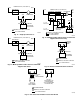
7. Check switch and light circuit by applying electrical power to
plug on power door. This can be accomplished with jumpers
from cabinet receptacle. Attach grounding wire between
power door base and cabinet.
A possible shock hazard exists. Be careful not to short out the
power supply. The buss bar and contact plate carry live high
voltage current on — 7300vdc, 1 MA.
The LED light circuit output can be checked with a voltmeter. The
reading should be 4vac.
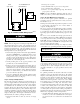
8. Check power supply.
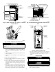
a. Place screwdriver on ground plate (access panel). At the
same time move shank portion of screwdriver towards
high-voltage output of power supply. If arcing occurs when
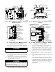
Fig. 25—Checking 120-V Power Pack
A91478
11