
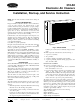
Instruction manual

Be sure all incoming power is off before beginning any
procedures.
A. INTERNAL ELECTRICAL CONNECTIONS
Proceed as follows to make internal electrical connections.
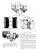
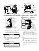
1. With power door removed, remove junction box cover adja-
cent to female plug on casing upper channel. (See Fig. 10.)
2. Install protective bushing from inside the air cleaner into the
upper hole on the side channel adjacent to the furnace. Be sure
bushing projects into furnace opening protecting wires from
sharp edges on cabinet opening.
3. Install protective bushing through top rail as shown in Fig. 10.
4. Plug unused hole on top of unit with plug provided in parts
bag.
5. Route power wires through bushing channel at top of cabinet,
down side channel, and through bushing in side channel and
into furnace opening. (See Fig. 10.)
6. Replace cover of junction box.
7. Install wire cover (provided in parts bag) under top flange and
secure to side channel with screw provided.
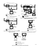
8. Connect power leads as follows:
a. Single Speed Furnaces—EAC is wired in parallel with fan
motor. (See Fig. 11.)
b. Multispeed Direct-Drive Motor—If the EAC is wired to
a multispeed direct-drive motor, it must be isolated by a
relay or sail switch. Use either air cleaner relay P/N
P283-1203 or sail switch P/N 69105D1. (See Fig. 12 or
13.)
c. Furnaces with Printed-Circuit Boards—EAC is wired to
furnace terminals EAC 1 and EAC 2. See Fig. 14 for wiring
connections.
9. Connect ground wire to base unit ground.
NOTE: For non-corporate furnaces, wire unit using conduit and
strain relief the wires.
Be sure all internal wiring connections are tight before power
is returned to the unit.
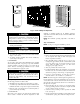
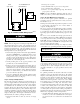
B. EXTERNAL ELECTRICAL CONNECTIONS
1. Attach power supply conduit to hole in top of EAC. Do not
use extension cord to connect to electrical power source.
2. Cut EAC wires to 6 in. long. Strip the ends. Using field-
supplied wire nuts connect power leads to black and white
pigtails extending from female receptacle. (See Fig. 10.)
NOTE: Do not connect aluminum conductor to electrical connec-
tions of the EAC. Use copper wire only.
3. Connect power leads as follows:
a. Single-Speed Furnaces. EAC is wired in parallel with fan
motor. (See Fig. 11.)
b. Multispeed Direct-Drive Furnaces. If the EAC is wired
to a multispeed direct-drive motor, it must be isolated by a
relay or sail switch. Use either air cleaner relay P/N
P283-1203 or sail switch P/N 69105D1. (See Fig. 12 or
13.)
c. Fan Coils. EAC (120v) MUST be wired to fan coil circuit
board terminals EAC 1 and EAC 2, if applicable, ONLY as
shown in Fig. 15. Terminals EAC 1 and EAC 2 supply
240vac. Terminal EAC 1 is energized continuously; termi-
nal EAC 2 is energized only with the fan motor.
4. Connect EAC ground wire (green) to appropriate supply
ground.
5. Replace cover of junction box.
Single-Speed Furnaces—Wire EAC in parallel with fan motor.
(See Fig. 11.)
Multispeed direct-drive furnaces—If the air cleaner is wired to
a multispeed direct-drive motor, it must be isolated by a relay or
sail switch. Use with either air cleaner relay P/N P283-1203 or sail
switch P/N 69105D1 (See Fig. 12 or 13).
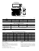
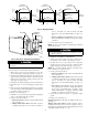
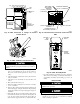
Fig. 5—Opening Detail
A91471
18
5
⁄8″
17
1
⁄4″
16
1
⁄4″
3
1
⁄4″
2
3
⁄4″
2
7
⁄16″
1
3
⁄4″
0
0
4
1
⁄4″ 5
3
⁄4″
5
1
⁄16″
25″
28
1
⁄2″
REAR OF
FURNACE
REAR OF
FURNACE
REAR OF
FURNACE
1
⁄8 IN.
DIA HOLE
FURNACE
KNOCKOUTS
1
⁄8 IN.
DIA HOLE
18
5
⁄8″
17
1
⁄4″
16
1
⁄4″
3
1
⁄4″
2
3
⁄4″
2
7
⁄16″
1
3
⁄4″
0
0
4
1
⁄4″ 5
3
⁄4″
5
1
⁄16″
28
1
⁄2″
1
⁄8 IN.
DIA HOLE
FURNACE
KNOCKOUTS
27
1
⁄2″
28
1
⁄2″
27
1
⁄2″
1
5
⁄16″
0
0
13
⁄16″
1
3
⁄4″
2
7
⁄16″
2
3
⁄4″
10
1
⁄2″
15
5
⁄8″
17
1
⁄4″
18
5
⁄8″
16
1
⁄4″
020
1
⁄8 IN.
DIA HOLE
FURNACE
KNOCKOUTS
016012
1
⁄8 IN.
DIA HOLE
1
⁄8 IN.
DIA HOLE
3
⁄4 IN.
DIA HOLE
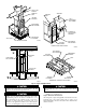
Fig. 6—Electronic Air Cleaner Installation
A89117
PLUG
FLANGE
FURNACE
OPENING
SCREWS
BUSHINGS
SCREWS
SCREWS
5