
Instruction manual

Fan Coils—EAC (120v) MUST be wired to fan coil circuit board
terminals EAC 1 and EAC 2 if applicable, ONLY as shown in Fig.
15. Terminals EAC 1 and EAC 2 supply 240vac. Terminal EAC 1
is energized continuously. Terminal EAC 2 is energized only with
the fan motor.
FINAL ASSEMBLY
Kit No. KFAIR0101ACR is offered for use when 24vdc relays
may not be available. The kit contains a 24vdc relay which mounts
directly inside the EAC cabinet. User supplied 110vac is activated
be this relay to power the air cleaner when G or W are present.
This preferred connection allows low-voltage wiring to be run
between the fan coil and the air cleaner and eliminates the
problems of controlling a 110vac air cleaner from the 230v power
supplied by the fan coil. (See Fig. 16.)
The ICM2 blower motor used in the FK4B Fan Coil is controlled
by low-voltage signals. The familiar 230vac air cleaner
control/power signal, EAC 1 and EAC 2, is not available. These
signals are replaced by a 24vdc signal which is provided at circuit
board terminals AUX 1 and AUX 2. This 24vdc signal is present
when either G or W is present and is active in all heating and
cooling modes.
In heat pump applications, the G signal is present in both cooling
and heating modes, permitting the EAC to be controlled from the
G signal only. For the application, a user supplied 24vac relay can
be driven by the G terminal, eliminating the need for the relay kit.
The selection and mounting of this AC relay is the responsibility
of the installer.
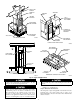
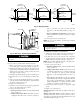
Fig. 7—Installing Baffles if Needed
A91472
BAFFLES
FURNACE
ELECTRONIC
AIR CLEANER
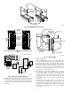
Fig. 8—Reversing Components for Opposite Air-
flow
A91473
IONIZER
WIRES
PREFILTERS
PROPER
CONTACT
SPRING
LOCATION
CHARGED
COLLECTOR
PLATES
AIRFLOW AIRFLOW
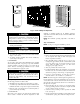
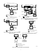
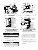
Fig. 9—Line-to-Line Wiring Diagram
A89073
UNIT
POWER
SUPPLY
Y
BLU
BLU
BLU
BLU
LED
WHT
LINE
VOLTAGE
BLK
HIGH
VOLTAGE
BLK
WHT
*
TRANSFORMER
ASSY. FOR
FIELD CONN.
BLK
WHITE
POWER
SWITCH
INTERLOCK
(DO NOT
BYPASS)
WIRE CONN.
BLK
WHITE
GREEN FIELD WIRED
GROUND
FIELD WIRING
*
ON 208/240 UNITS ONLY
OPERATION LIGHT
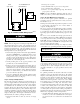
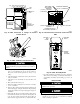
Fig. 10—Wire Routing
A94155
TOP PLUG
WIRE COVER FOR
CHANNEL
INTERNAL
POWER WIRE
ROUTING
GROUND
FURNACE
CONTROL
BOARD
BUSHING HOLES
FURNACE
BUSHING HOLES
6