
Instruction manual
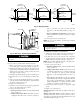

a. Place electronic cells on sides with ionizer section down
(airflow arrows pointing up) on lower rack of dishwasher.
Use care to avoid damage to the collector plates when placing
the cells in the dishwasher.
NOTE: For some dishwashers with a center spray arm, it may be
necessary to remove the top basket to fit one or both cells inside.
b. Use detergent in accordance with dishwasher manufactur-
er’s instructions.
c. Allow dishwasher to run through its complete wash cycle.
You may also allow it to run through its complete dry
cycle, although this is not necessary.
The electronic cell will be very hot at the end of the
dishwasher’s cycle. Allow it to cool before handling. Hot
water may accumulate in the tubes supporting the collector
plates. Tip the cells to drain tubes.
d. Dry cells completely before turning on power to air
cleaner. This can be done by replacing cells in cabinet and
turning on system fan continuously for approximately 30 to
60 minutes before restoring power to air cleaner.
e. With some dishwashers it may be necessary to re-run
complete cycle or rinse cycle after cells are removed if
homeowner notices dirt stains or residue inside dishwasher.
2. Manual Washing—The electronic cells may be washed manu-
ally by soaking them in a solution of automatic dishwasher
detergent.
a. Provide suitable container large enough to hold one or both
cells.
b. Select automatic dishwasher detergent that dissolves
readily in hot water. Depending on local water conditions,
some brands may form a precipitation or scum. If a
noticeable scum floats to surface, try another brand. The
brand the homeowner finds gives the best results in his
dishwasher will probably give best results washing the
electronic cells.
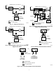
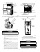
Fig. 19—EAC Connection to Multipoise Fixed
Capacity Furnace Control Board
A94081
HUM-HUMIDIFIER
TERMINAL
(24-VAC 0.5 AMP MAX)
LED OPERATION
& DIAGNOSTIC LIGHT
HARNESS
CONNECTOR
24V TRASFORMER
SEC-2
SPARE 1
SPARE 2
EAC 1 (BLACK)
EAC-ELECTRONIC AIR
CLEANER TERMINALS
(115-VAC 1 AMP MAX)
EAC 2 (WHITE)
115-VAC (L2) NEUTRAL
CONNECTION
24-VOLT
THERMOSTAT
TERMINALS
HEAT
COOL
BLOWER OFF-DELAY
ADJUSTMENT SWITCH
SEC-1
G
R
Y
W
Com
3-AMP FUSE
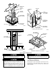
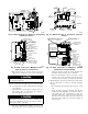
Fig. 17—EAC Connection to Electronic Condensing
Upflow Gas Furnace
A91490
ACCR
CIRCUIT
BREAKER
R Y W G C
Fig. 20—EAC Connection to Multipoise Variable
Speed Furnace Control Board
A94082
EAC-ELECTRONIC AIR CLEANER
TERMINALS (115-VAC
1 AMP MAX)
MAIN BLOWER
CONTROL WIRE
CONNECTOR
CONTINUOUS
FAN (CF) SETUP
SWITCHES
HOT SURFACE
IGNITOR CONNECTOR
HUM-HUMIDIFIER
TERMINAL (24-VAC
0.5 AMP MAX)
24-VOLT
THERMOSTAT
TERMINALS
TRANSFORMER
24-VOLT
CONNECTIONS
3-AMP FUSE
STATUS AND
DIAGNOSTIC
LED LIGHTS
SETUP SWITCHES
(SW) AND
BLOWER OFF DELAY
SETUP SWITCHES
Fig. 18—EAC Connection to Continuous Pilot Gas
Furnace
A91226
MAX. 1.0 AMPS
115-VAC
SEC-2
SEC-1
GROUND
SCREW
REQUIRED
FU
3-AMP
FUSE
BLOWER
OFF-DELAY
24-VAC
COMMON
CES0110074-00
W Y R C G
EAC-2
EAC-1
COM PR-2 L2
CFR
HI
HFR
L1
PR-1
PL-1
1
2
3
4
5
6
7
8
9
1
3
IDR
24-VAC COMMON
BLOWER
OFF-TIME
ADJUSTMENT
24-VAC
THERMOSTAT
TERMINALS
COOLING
SPEED TAP
TERMINAL
HEATING
SPEED TAP
TERMINAL
115-VAC
NEUTRAL
TERMINALS
115-VAC
LINE
VOLTAGE
115-VAC
TRANSFORMER
9-PIN
CONNECTOR
ELECTRONIC
AIR-CLEANER
TERMINALS
24-VAC POWER
LO
24-VAC FUSE
3-AMP ONLY
UNCUT: 120 SEC
CUT: 180 SEC
9