
Installation manual

38GL_M…G
R-410A
GB - 3
ENGLISH
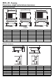
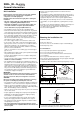
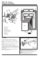
햲 Outdoor unit
햳 Indoor unit circuit A
햴 Indoor unit circuit A
햵 Indoor unit circuit B
햶 Indoor unit circuit B
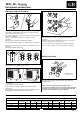
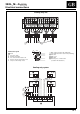
Connections and operating limits
햲
햳
햴
A
/ A
1
A
2
H
H
L1
L2
햴
A
2
H
햵
B
/ B
1
H
햶
B
2
H
L3
L4
햲
햳
햶
햵
A
/ A
1
B
/ B
1
B
2
H
H
L1
L
2
L3
L4
햴
A
2
H
H
Connections
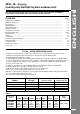
Notes: 1. Data referred to the outdoor unit only.
2. According to ISO 5151.2/T1.
3. For lower temperatures use low-ambient kit
A
B
A1
A2
B
A2
B1
B2
A1
A1
A2
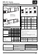
Pipe diameter
Liquid Gas
Model Indoor (Liquid) (Suction)
38GL unit mm (inches) mm (inches)
2M12G
A1 6.35 (1/4") 9.52 (3/8")
A2 6.35 (1/4") 12.70 (1/2") (note 1)
2M18G
A 6.35 (1/4") 9.52 (3/8")
B 6.35 (1/4") 9.52 (3/8")
2M24G
A 6.35 (1/4") 12.70 (1/2")
B 6.35 (1/4") 12.70 (1/2")
A1 6.35 (1/4") 9.52 (3/8")
3M21G A2 6.35 (1/4") 12.70 (1/2") (note 1)
B 6.35 (1/4") 9.52 (3/8")
A1 6.35 (1/4") 9.52 (3/8")
4M24G
A2 6.35 (1/4") 12.70 (1/2") (note 1)
B1 6.35 (1/4") 9.52 (3/8")
B2 6.35 (1/4") 12.70 (1/2") (note 1)
Notes
1) When the indoor unit is as large as 009, use 9.52 mm (3/8”) pipes
with the flare tap adapter supplied.
Important: do not connect the indoor unit size 012 to the circuit B.
2) All fittings are flare type.
3) Use only refrigeration grade pipes, (Cu DHP type according to
ISO 1337), seamless, degreased, deoxidized and suitable for
operating pressures of at least 4200 kPa.
Under no circumstances must sanitary type annealed copper pipe
be used.
38GL2M12G 38GL2M18G
38GL2M24G
38GL3M21G
38GL4M24G
d.b. - dry bulb
w.b. - wet bulb
Table III: Operating limits
(1)
Cooling (2)
Maximum conditions
Outdoor temperature 43°C
Indoor temperature 32°C d.b.; 23°C w.b.
Minimum conditions
Outdoor temperature 21°C (3)
Indoor temperature 21°C d.b.; 15°C w.b.
Mains power supply Nominal single-phase voltage 230V ~ 50Hz
Operating voltage limits min. 198V – max. 264V
Minimum nominal thickness
Pipe diameter Minimum nominal thickness
inches - mm mm
1/4” - 6.35 0.80
3/8” - 9.52 0.80
1/2” - 12.70 0.80
Table II: Connections
Model 38GL
2M12G 2M18G 2M24G 3M21G 4M24G
Max. height difference
H m55555
Max.
pipe length L1 m – 15 15 – –
L2 m–––––
L3 m – 15 15 15 –
L1 + L2 m15 – – 15 30
L3 + L4 m– – – – 30
Differenza max L1 - L2 m5––55
L3 - L4 m––––5
(Minimum number of bends possible)
Refrigerant charge
R-410A
- No refrigerant to be added
max max max max max
for pipe length up to
mmmmm
A = Circuit A 15 8A +8A +8A +15A +
B = Circuit B 8B 8B 15B 15B
- For longer pipes add
refrigerant, grams/meter
–1515–15