38GL...G9 38YY...G9 / 38YYS...
For operation and maintenance instructions of this unit as well as installation instructions of the indoor unit, refer to the relevant manuals. Contents Dimensions and weight ................................................................................................................. Connections .................................................................................................................................. Minimum clearances ............................................................
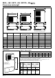
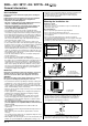
8GL...G9 / 38YY...G9 / 38YYS...G9 Dimensions and weight A A A B B E D E E D E F C C 38GL018G9 F E 38GL024G9 D E F C Mod. 38GL028G, 036G Mod. 38YY-028G9, 036G9 Mod. 38GL018G9, 024G9 A B C D E F B Mod. 38GL048G9, 052G9, 060G9 Mod.
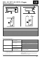
38GL...G9 / 38YY...G9 / 38YYS...G9 Minimum clearances ENGLISH D A C B E E D Mod. 18 24 28 36 48 52 60 A mm 100 100 100 100 100 100 100 B mm 250 250 250 250 250 250 250 C mm 500 500 500 500 500 500 500 D mm 50 50 100 100 100 100 100 E mm 470 470 670 670 670 670 670 F mm 400 400 400 400 400 400 400 Table III: Operating limits (1) Cooling (2) Maximum conditions Outdoor temperature 43°C Indoor temperature 32°C d.b.; 23°C w.b.
38GL...G9 / 38YY...G9 / 38YYS...G9 General information Read this instruction manual thoroughly before starting the installation. R-410A systems operate at higher pressures than standard R-22 systems. Do not use R-22 service equipment or components on R-410A equipment. • This unit complies with low-voltage (EEC/73/23) and electromagnetic compatibility (EEC/89/336) directives.
38GL...G9 / 38YY...G9 / 38YYS...G9 Warnings: avoid.... ENGLISH Disconnecting the refrigerant connections after installation: this will cause refrigerant leaks. Connecting the condensate drain pipe to the outdoor unit. Excessive height difference between indoor and outdoor unit (see Table II "Connections"). Excessive distance between indoor and outdoor units. (see Table II "Connections"). Predominant head winds. Unnecessary turns and bends in the connecting pipes.
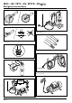
38GL...G9 / 38YY...G9 / 38YYS...G9 Refrigerant connections No moisture. No dust. Charge liquid-no gas. No leak. No mineral oil. Copper tubes during storage. Neat. 1/2” UNF (R-410A) Use tools designed for R-410A higher pressure. Keep inside clean. Dry nitrogen brazing. Min. – 100 kPa (– 755 mmHg) Vacuum. GB - 6 2-stage vacuum pump. Replace oil regularly.
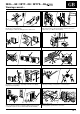
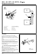
38GL...G9 / 38YY...G9 / 38YYS...G9 Refrigerant connections ENGLISH Flaring the ends of the tubing 2 1 The unit can be installed: 햲 on the floor; 햳 on the wall using the bracket kit. Remove protective caps from copper tube ends. Position tube end downward, cut the tube to the requested length and remove the burrs with a reamer. Do not leave system open to atmosphere any longer than minimum required for installation. Oil in the compressor is extremely susceptible to moisture absorption.
38GL...G9 / 38YY...G9 / 38YYS...G9 Refrigerant connections ! 햷 햻 햶 햹 햸 햵 햺 햴 햸 햾 햹 햳햲 햴 햽 햲 Three-way valve 햸 Gas line (large diameter) 햳 Needle valve 햹 Liquid line (small diameter) 햴 Valve cap 햺 Flare nut 햵 Valve needle 햻 Indoor unit 햶 Two-way valve 햽 Outdoor unit 햷 Allen (hex. head) wrench 햾 Vacuum pump Air purging Use only a vacuum pump to purge air from the piping. NEVER use the system compressor as a vacuum pump. NEVER use the unit refrigerant gas to purge the connecting pipes.
38GL...G9 / 38YY...G9 / 38YYS...
38GL...G9 / 38YY...G9 / 38YYS...G9 Electrical connections • Before proceeding with the unit connection to the mains supply locate live L1, L2, L3 and neutral N, then make connections as shown in the wiring diagram. • According to the installation instructions, the disconnecting switches from the mains power supply should have a contact gap (4 mm) such that total disconnection can be ensured under the conditions provided for by overvoltage class III.
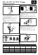
38GL...G9 / 38YY...G9 / 38YYS...G9 Pump Down and check the refrigerant charge ENGLISH Pump-down Check the refrigerant charge Pump-down is an operation intended to collect all the system refrigerant in the outdoor unit.
38GL...G9 / 38YY...G9 / 38YYS...G9 Unit maintenance and troubleshooting Unit maintenance The following maintenance operations must be carried out by qualified personnel. Cleaning the coil When necessary, proceed as follows for more careful cleaning of the coil: Switch the mains supply OFF. Remove unit top cover by loosening holding screws and lifting the cover. Carefully clean the coil with a vacuum cleaner from inside to outside.
38YYS...G9 Installation instructions supplement ENGLISH Heat pump unit Outdoor unit Indoor unit 햲 햳 햴 햵 햶 햷 Temperature sensor High pressure cut-out (HIP) Loss of refrigerant pressure switch (LRPS) Crankcase heater Pressure service port Head pressure controller (HPC) 38YYS...G9 units are designed to work in North European countries climates and where cooling is required, even in case of outdoor low temperatures.
38YYS...G9 Installation instructions supplement Condensing temperature controller: wiring diagram SENSOR temperature sensor 10FM 1FC SENSOR CONTROL N. OUT CONTROL N.
L010127H17 - 1105 Via R. Sanzio, 9 - 20058 Villasanta (MI) Italy - Tel. 039/3636.1 The manufacturer reserves the right to change any product specifications without notice. November, 2005.