
Installation manual


GB - 9
38GL...G9 / 38YY...G9 / 38YYS...G9
ENGLISH
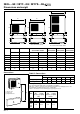
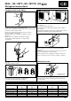
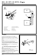
Electrical connections
Terminal box legend, all models
Earth
L1 Live power supply
L2 Live power supply
L3 Live power supply
N Neutral power supply
R Live connection indoor/outdoor unit
C Neutral connection indoor/outdoor unit
Y Compressor interlocking contact
O Reversing valve control (Heat pump only)
W2 Outdoor fan signal (Heat pump only)
S Defrost end signal
Cooling only unit Cooling only system
Heat pump unit
Heat pump system
L1 N R C Y
L2
L3
O
W
2
S
L1 N R C Y
L2
L3
O
W
2
S
햵
햴
햲
L1 N
L3 N
RCY
햲
햳
L2
L3
L1 L2
RCY
RCY
O
W
2
S
L1
NR
CY
L3
L2
400V 3N ~ 50Hz
RCY
O
W
2
S
L1
NR
CY
L3
L2
400V 3N ~ 50Hz
O
W
2
S
햲
햳
햴
햵
10
120
10 100
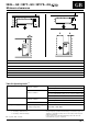
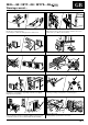
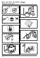
햲 Mains supply connecting cable
(field wiring).
햳 Connecting cable Outdoor unit – Indoor unit
(R - C - Y - ) - (field wiring).
햴 Connecting cable Outdoor unit – Indoor unit
(Y - O - W
2
- S) - (field wiring).
햵 Connecting cable Outdoor unit – Indoor unit
(R - C - ) - (field wiring).
쐃 Indoor unit
쐇 Outdoor unit
쐋 Main switch
쐏 Time-delay fuse or circuit breaker
(see table IV "Electrical data").