
Installation manual


38GL...G9 / 38YY...G9 / 38YYS...G9
GB - 10
Electrical connections
Unit AAWAWAWAWA mm
2
38GL018G9 24 3.8 1950 5.0 2600 –– –– 10 2.5
38GL024G9 32 4.5 2270 5.9 3060 –– –– 10 2.5
38GL028G9 37 4.8 2880 6.7 3450 –– –– 16 2.5
38GL036G9 39 5.2 3320 7.1 3800 –– –– 16 2.5
38GL048G9 54 6.8 3540 8.3 3950 –– –– 16 2.5
38GL052G9 64 9.1 4300 11.1 5420 –– –– 25 2.5
38GL060G9 64 8.6 4900 11.1 5480 –– –– 25 2.5
38YY(S)028G9 37 5.7 3100 7.3 3700 5.2 2640 7.0 3670 16 2.5
38YY(S)036G9 39 6.6 3470 8.3 4250 5.9 2960 7.8 3890 16 2.5
38YY(S)048G9 54 7.3 3540 8.4 4060 7.2 3490 8.9 4380 16 2.5
38YY-052G9 64 9.3 4380 11.3 5300 9.5 4450 11.4 5430 25 2.5
38YY(S)060G9 64 10.5 5220 12.1 5905 9.7 4620 11.5 5630 25 2.5
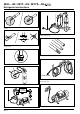
• Make refrigerant connections before electrical
connections.
When disassembling, disconnect electrical connections before
refrigerant connections.
IMPORTANT:
Make ground connection prior to any other electrical
connections.
• Remove electric box cover.
• Connect the wires to the terminals according to the wiring
diagram and firmly tighten.
• Make electrical connections between units prior to proceeding
to mains supply unit connection.
Table IV: Electrical data
Starting
current
(3)
Heating
Cooling
Main power
connections
(6)
Time-delay
fuse
gL type
Wire size
(4-5)
Nominal conditions
400V
~
50Hz
ISO 5151.2/T1
indoor 27°C d.b. 19°C w.b.
outdoor 35°C d.b. 24°C w.b.
Peak conditions
342V
~
50Hz
ISO 5151.2/T1
indoor 32°C d.b. 23°C w.b.
outdoor 43°C d.b. 32°C w.b.
Nominal conditions
400V
~
50Hz
ISO 5151.2/High+
indoor 20°C d.b. 15°C w.b.
outdoor 7°C d.b. 6°C w.b.
Peak conditions
342V
~
50Hz
ISO 5151.2/High+
indoor 27°C
outdoor 24°C d.b. 18°C w.b.
Power input
(2)
Notes: 1. Unit is suitable for outdoor installation.
2. Data referred to the outdoor unit only.
3. Starting current duration is usually lower than 1 sec.
4. Wire size shown applies to line length up to 15 m.
5. If the indoor unit is provided with an electric heater, consult indoor unit installation manual for correct sizing of the wires.
6. The mains supply connecting cable must be H07 RN-F (60245IEC66) type, synthetic rubber insulation with Neoprene coating.
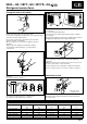
• Before proceeding with the unit connection to the mains supply
locate live L1, L2, L3 and neutral N, then make connections as
shown in the wiring diagram.
• According to the installation instructions, the disconnecting
switches from the mains power supply should have a contact gap
(4 mm) such that total disconnection can be ensured under the
conditions provided for by overvoltage class III.
• The mains supply indoor unit – outdoor unit connecting cable
must be H07 RN-F (60245IEC66), type synthetic rubber insulation
with neoprene coating.
• When the electric supply cables L1 (R), L2 (S), L3 (T) are
connected inversely, a special “PSC” phase inversion protection
device blocks the compressor to prevent the same from rotating
inversely.
In this case, switch off the electrical supply and check the
correctness of the sequence of the cables of the supply line
connected to the main terminal block (they are probably inverted).
The compressor will only be allowed to work if the phase
sequence is correct.
The phase sequence protection device also continuously monitors
the electrical supply line and if one of the phases is completely
missing it blocks the compressor.
The device only re-starts the compressor after the supply line is
correctly restored.
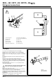
All the three phase compressors have identical internal wiring.
For this reason when the correct phase connections for a specific
system have been determined, the rotation direction will always
be correct if the same connections are made to the terminal block
(for the other equipment).
Note:
All field electrical connections are the responsibility of the
installer.
Refer to the indoor unit installation manual for sizing the
connection wires between units.
Note:
After connections have been completed, replace electric box
cover.