
Installation Instructions
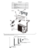
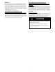
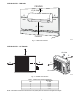
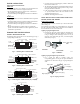
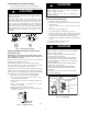
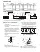
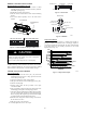
Table Of Contents

10
REMOTE CONTROL INSTALLATION
Mounting Bracket (if installed on the wall)
1. Use the two screws supplied with control to attach
mounting bracket to wall in location selected by customer
and within operating range.
2. Install batteries in the remote control.
3. Place the remote control into the remote control mounting
bracket.
4. For remote control operation, refer to the unit owner’s
manual.
LNS L1 L2 S
9K and 12K 115V 12K to 22K 208-230V
Electrical box
cover
Front Panel
A14352
Fig. 18 - Control and Power Wiring on Indoor Unit
UNIT DAMAGE HAZARD
Failure to follow this caution may result in equipment
damage or improper operation.
Never use the system compressor as a vacuum pump.
CAUTION
!
Refrigerant tubes and indoor coil should be evacuated using the
recommended deep vacuum method of 500 microns. The alternate
triple evacuation method may be used if the procedure outlined
below is followed. Always break a vacuum with dry nitrogen.
SYSTEM VACUUM AND CHARGE
Using Vacuum Pump
1. Completely tighten the flare nuts A, B, C, D, connect the
manifold gage charge hose to a charge port of the low side
service valve (see Fig. 19).
2. Connect the charge hose to the vacuum pump.
3. Fully open the low side of the manifold gage (see Fig. 20).
4. Start the vacuum pump.
5. Evacuate using either the deep vacuum or the triple
evacuation method.
6. After evacuation is complete, fully close the low side of the
manifold gage and stop the vacuum pump operation.
7. The factory charge contained in the outdoor unit is good for
up to 25 ft. (8 m) of line length. For refrigerant lines longer
than 25 ft. (8 m), add refrigerant, up to the allowable length,
as specified in the System Requirements section.
8. Disconnect the charge hose from the charge connection of
the low side service valve.
9. Fully open service valves B and A.
10. Securely tighten the service valves caps.
Outdoor Unit
Indoor Uni
t
Refrigerant
Service Valve
Low Side
High Side
A
B
C
D
A07360
Fig. 19 - Service Valve
Manifold Gage
500 microns
Low side valve
High side valve
Charge hose
Charge hose
Vacuum pump
Low side valve
A07361
Fig. 20 - Manifold
Deep Vacuum Method
The deep vacuum method requires a vacuum pump capable of
pulling a vacuum of 500 microns and a vacuum gage capable of
accurately measuring this vacuum depth. The deep vacuum method
is the most positive way of assuring a system is free of air and
liquid water (see Fig. 21).
500
MINUTES
01234567
1000
1500
LEAK IN
SYSTEM
VACUUM TIGHT
TOO WET
TIGHT
DRY SYSTEM
2000
MICRONS
2500
3000
3500
4000
4500
5000
A95424
Fig. 21 - Deep Vacuum Graph