
Installation Instructions
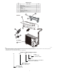
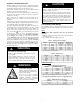
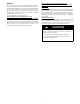
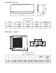
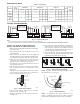
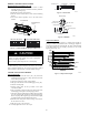
Table Of Contents

2
PARTS LIST
Part
No.
Name of Part Qty
1 Indoor Unit 1
2 Mounting Plate 1
3 Mounting Screw A ST3.9x25-C-H 5
4 Anchor 5
5 Air Filter 1
6 Remote Control 1
7 Remote Control Holder 1
8 Mounting Screw B ST2.0x10-C-H 2
9 Outdoor Unit 1
■ Indoor
■ Outdoor
Air Outlet
S
e
l
f
C
l
e
a
n
F
ol
l
ow
M
e
L
E
D
T
u
r
b
o
I
o
n
i
z
er
S
ma
r
t
E
y
e
S
i
l
e
n
c
e
M
o
d
e
O
n/
O
f
f
F
a
n
S
l
e
e
p
S
w
i
n
g
T
i
m
e
r
T
E
M
P
A
U
T
O
C
O
O
L
D
R
Y
H
E
A
T
F
A
N
H
I
G
H
M
E
D
L
O
W
F.P.
1
5
9
6
8
7
2
3
4
A14342
Note:
- If the outdoor unit is higher than the indoor unit, prevent rain from flowing into the indoor unit along the connection pipe by making a downward arc in the connection pipe before it
enters the wall to the indoor unit. This ensures that rain will drip from the connection pipe before it enters the wall.
- Piping and the interconnecting wiring are field supplied.
- The illustration above is only a sketch. Different models may be slightly different.
MODEL NUMBER NOMENCLATURE
38 MFC 009 - - - 1
Voltage
1 = 115-1-60Hz;
3 = 208-230-1-60Hz
Blank
System’s nominal capacity in 1000 BTU/Hr
Example: 009 = 9000 BTU/Hr
System’s type:
MFC = Air Conditioner;
MFQ = Heat pump
Equipment type:
40 = Indoor unit;
38 = Outdoor unit