
Installation Instructions
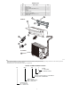
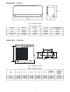
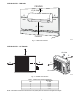
Table Of Contents

7
INSTALLATION TIPS
Ideal installation locations include:
Indoor Unit
S A location where there are no obstacles near inlet and outlet area.
S A location which can bear the weight of indoor unit.
S Do not install indoor units near a direct source of heat such as
direct sunlight or a heating appliance.
S A location which provides appropriate clearances as outlined in
Fig. 3.
Outdoor Unit
S A location which is convenient to installation and not exposed to
strong wind.
S A location which can bear the weight of outdoor unit and where
the outdoor unit can be mounted in a level position.
S A location which provides appropriate clearances as outlined in
Fig. 4.
S Do not install the indoor or outdoor units in a location with
special environmental conditions. For those applications, contact
your Ductless representative.
INDOOR UNIT INSTALLATION
INSTALL MOUNTING PLATE
The mounting plate will look like one of the following (see Fig. 5
− 8) depending on model size:
Left rear side
refrigerant pipe
hole ¶2.6 (65)
Right rear side
refrigerant pipe
hole ¶2.6 (65)
6 (150) or more to ceiling
5 (130)
or more to wall
5 (130)
or more to wall
Indoor unit outline
26.8 (680)
6.7 (170)
3.6 (92)
10(255)
in. (mm)
A14345
Fig. 5 - Mounting Plate− Model size 009
Indoor unit outline
Left rear side
refrigerant pipe
hole ¶2.6 (65)
5 (130)
or more to wall
30.3 (770)
6.7 (170)
3.7 (95)
10 (255)
Left rear side
refrigerant pipe
hole ¶2.6 (65)
6 (150) or more to ceiling
5 (130)
or more to wall
1.8 (45)
1.8 (45)
in. (mm)
1.6 (41)
A14346
Fig. 6 - Mounting Plate− Model size 012
Indoor unit outline
10.8 (275)
Left rear side
refrigerant pipe
hole ¶2.6 (65)
5 (130)
or more to wall
1.4 (36.5)
35.6 (905)
3.2 (80)
3.9 (100)
Left rear side
refrigerant pipe
hole ¶2.6 (65)
6 (150) or more to ceiling
5 (130)
or more to wall
in. (mm)
1.8 (45)
A14347
Fig. 7 - Mounting Plate− Model sizes 017 (AC) / 018 (HP)
Left rear side
refrigerant pipe
hole ¶2.6 (65)
5 (130)
or more to wall
0.8 (21.5)
Installation plate
Indoor unit outline
40.6 (1030)
11.5 (292) 6.4 (163)
12.4 (315)
1.8 (45)
Left rear side
refrigerant pipe
hole ¶2.6 (65)
6 (150) or more to ceiling
5 (130)
or more to wall
in. (mm)
A14348
Fig. 8 - Mounting Plate− Model size 022
1. Carefully remove the mounting plate, which is attached to
the back of the indoor unit.
2. The mounting plate should be located horizontally and level
on the wall. All minimum spacings shown in Fig. 3 and 5
through 8 should be maintained.
3. If the wall is block, brick, concrete or similar material, drill
.2” (5 mm) diameter holes and insert anchors for the
appropriate mounting screws.
4. Attach the mounting plate to the wall.
DRILL HOLE IN WALL FOR INTERCONNECTING
PIPING, DRAIN AND WIRING
Refrigerant Line Routing
The refrigerant lines may be routed in any of the four directions
shown in Fig. 10.
For maximum serviceability, it is recommended to have refrigerant
line flare connections and the drain connections on the outside of
the wall that the fan coil can be mounted on.
If piping is going through the back:
1. Determine the pipe hole position using the mounting plate
as a template. Drill the pipe hole diameter per values given
in Fig. 5 through 8. The outside pipe hole is 1/2−in. (13
mm) min. lower than inside pipe hole, so it slants slightly
downward (see Fig. 9).
1/2 in. (13 mm
)
Min.
I
NDOOR
OUTDOOR
A07371
Fig. 9 - Drill Holes
If piping is going through the right or left side:
1. Use a small saw blade to carefully remove the
corresponding plastic covering on side panel and drill the
appropriate size hole where the pipe is going through the
wall.
Pipe holder
Pipe cover
Right piping
Left piping
Pipe cover
Right back piping
Left back piping
1
2
3
4
A14349
Fig. 10 - Piping Locations