
Installation Instructions
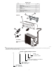
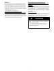
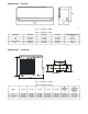
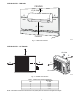
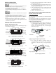
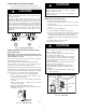
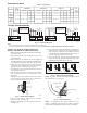
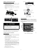
Table Of Contents

9
ELECTRICAL DATA
Table 8 – Electrical Data
UNIT SIZE
OPER.
VOLTAGE
MAX
/ MIN
COMPRESSOR OUTDOOR FAN INDOOR FAN
MCA
MAX
FUSE
CB
AMP
V-PH-HZ RLA LRA V-PH-HZ FLA HP W V-PH-HZ FLA HP W
9K
127 / 104 115-1-60 5.30 10 115-1-60 0.7 0.31 23 115-1-60 0.3 0.020 15 19 30
12K
12K
253 / 187 208-230-1-60
5.30 10
208-230-1-60
0.3 0.33 24
208-230-1-60
0.2 0.027 20 10 15
017K (HP)
/
018K
(AC)
3.95 14 0.6 0.68 50 0.3 0.038 28 14 20
22K 9.70 17 0.6 0.72 53 0.4 0.061 45 16 25
CONNECTION DIAGRAMS
S
L
N
115-1-60
Main
Power Supply
115-1-60
1(L)
2(N)
S
L
N
Power to
Indoor Unit
CONNECTING CABLE
OUTDOOR TO INDOOR
GND
Indoor Unit
Power Supply
Ground
Indoor
Signal
High
Voltage
115-1-60
115-1-60
FIELD POWER SUPPLY
GND
Indoor
Signal
High
Voltage
208-230-1-60
9K and 12k 115v INDOOR UNIT 9K and 12k 115v OUTDOOR UNIT
S
L1
L2
Main
Power Supply
208-230-1-60
L1
L2
S
L1
L2
Power to
Indoor Unit
CONNECTING CABLE
OUTDOOR TO INDOOR
GND
Indoor Unit
Power Supply
Ground
Indoor
Signal
High
Voltage
208-230-1-60
FIELD POWER SUPPLY
GND
Indoor
Signal
High
Voltage
12K to 22K 208-230V OUTDOOR UNIT12K to 22K 208-230V INDOOR UNIT
208-230-1-60
A14506
Fig. 14 - Connection Diagrams
Notes:
1. Do not use thermostat wire for any connection between indoor and outdoor units.
2. All connections between indoor and outdoor units must be as shown. The connections are sensitive to polarity and will result in a fault code.
INSTALL ALL POWER, INTERCONNECTING
WIRING, AND PIPING TO THE INDOOR UNIT
1. Run the interconnecting piping and wiring from the outdoor
unit to indoor unit.
2. Run the interconnecting cable through the hole in the wall
(outside to inside).
3. Lift the indoor unit into position and route the piping and
drain through the hole in the wall (inside to outside). Fit the
interconnecting wiring into the back side of the indoor unit.
4. Put the upper claw at the back of the indoor unit on the
upper hook of the mounting plate, move the indoor unit
from side to side to see that it is securely hooked.
5. Open the front cover of the indoor unit and remove the field
wiring terminal block cover.
6. Pull the interconnecting wire up from the back of indoor
unit and position in close to the terminal block on the
indoor unit.
7. Push the lower part of the indoor unit up on the wall, then
move the indoor unit from side to side, up and down to
check if it is hooked securely (see Fig. 15).
Upper hook
Lower hoo
k
A07347A
Fig. 15 - Indoor Unit Installation
8. Connect wiring from the outdoor unit per connection
diagram (see Fig. 14 and Fig. 18).
9. Replace the field wiring cover and close the front cover of
the indoor unit.
10. Connect the refrigerant piping and drain line outside of the
indoor unit. Refer to Fig. 12 for the proper installation of
flare connections. Complete the pipe insulation at the flare
connection then fasten the piping and wiring to the wall as
required. Completely seal the hole in the wall.
11. Connect the drain line. The drain line must not have a trap
anywhere in its length, must pitch downwards, and must be
insulated up to the outside wall (see Fig. 16).
Proper Do not put drain end into waterDo not form a rise
A14351
Fig. 16 - Proper Drain Hose Installation
NOTE: For proper orientation of the refrigerant piping, electrical
cable and drain lines, refer to Fig. 17.
Interconnecting
Wiring
Drain Piping
Refrigerant Piping
Tape
Indoor unit
.
.
.
.
.
.
.
.
.
.
.
.
.
.
.
.
.
.
.
.
.
.
.
.
.
.
.
.
.
.
..
.
A07346
Fig. 17 - Proper Orientation
NOTE: For applications where gravity cannot be used for
drainage, a condensate pump accessory is available. Consult the
condensate pump Installation Instructions for more information.