R QUALIT TE Y SURANC E AS • YD'S REGI S LO 38GL_M…G / 38YY(S)_M…G IS O 900 1 L R-410A INSTALLATION MANUAL
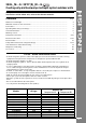
For operation and maintenance instructions of this unit as well as installation instructions of the indoor unit, refer to the relevant manuals. Contents Page Dimensions and weight ................................................................................................................. 2 Minimum clearances and connections ......................................................................................... 3 Connections ......................................................................
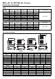
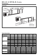
8GL_M…G / 38YY(S)_M…G R-410A Dimensions and weight Table I Cooling only models Hi-Wall 42PHQ-N 38GL2M12G(1) 38GL2M18G(1) 38GL2M24G(1) 38GL2M36G 38GL2M48G 38GL3M21G(1) 38GL4M24G 009 - 012 009 012 018 024 009 - 012 009 - 012 Console Cassette Satellite 42HMC-N 42VMC-N 40KMC-N 40SMC-N 009 - 012 009 012 018 024 009 - 012 009 - 012 009 - 012 009 012 018 024 009 - 012 009 - 012 012 012 018 024 012 012 009 - 012 009 012 018 024 009 - 012 009 - 012 Console Cassette Satellite 42VMC-N 009 009 - 01
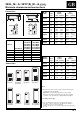
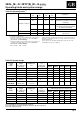
38GL_M…G / 38YY(S)_M…G R-410A Minimum clearances and connections Connections D A C B Model 38GL E A1 A2 6,35 6,35 (1/4") (1/4") 9,52 12,70 (3/8") (1/2") (note 1) 2M18G A B 6,35 6,35 (1/4") (1/4") 9,52 9,52 (3/8") (3/8") 2M24G A B 6,35 6,35 (1/4") (1/4") 12,70 12,70 (1/2") (1/2") 3M21G A1 A2 B 6,35 6,35 6,35 (1/4") (1/4") (1/4") 9,52 12,70 9,52 (3/8") (1/2") (note 1) (3/8") 4M24G A1 A2 B1 B2 6,35 6,35 6,35 6,35 (1/4") (1/4") (1/4") (1/4") 9,52 12,70 9,52 12,70 (3/8") (1/2"
38GL_M…G / 38YY(S)_M…G R-410A Connections Connections 햳 A / A1 햴 A2 L1 햶 B2 햵 B / B1 L4 L3 L2 H H H H 햲 L3 햲 L2 H H H 햶 B2 햵B / B1 햴 A2 L1 햳 A/A L4 H 1 햲 햳 햴 햵 햶 Outdoor unit Indoor unit circuit A Indoor unit circuit A Indoor unit circuit B Indoor unit circuit B Table II: Connections Model GL 2M12G 2M18G 2M24G 3M21G 4M24G 2M36G 2M48G Hm 5 5 5 5 5 10 15 Max.
38GL_M…G / 38YY(S)_M…G R-410A Operating limits and system charge ENGLISH Table III: Operating limits (1) Outdoor temperature °C Indoor temperature °C Cooling (2) Maximum conditions Applicable d.b. w.b. d.b. w.b. 43 – 32 23 All multisplit units 21 (3) – 21 15 38GL2M18G; 38GL2M24G; 38GL3M21G 15 – 21 15 38GL2M36G(4); 38GL2M48G(4); 38YY2M18G; 38YY2M36G;38YY2M48G; 38YY2M21G;38YY2M24G. -10 – 21 15 38YYS2M36G;38YYS2M48G.
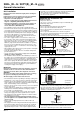
38GL_M…G / 38YY(S)_M…G R-410A General information Read this instruction manual thoroughly before starting the installation. R-410A systems operate at higher pressures than standard R-22 systems. Do not use R-22 service equipment or components on R-410A equipment. • This unit complies with low-voltage (EEC/73/23) and electromagnetic compatibility (EEC/89/336) directives.
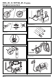
38GL_M…G / 38YY(S)_M…G R-410A Warnings: avoid.... ENGLISH Disconnecting the refrigerant connections after installation: thiis will cause refrigerant leaks. Connecting the condensate drain pipe to the outdoor unit. Excessive height difference between indoor and outdoor unit (see Table II "Connections"). Excessive distance between indoor and outdoor units. (see Table II "Connections"). Predominant head winds. Unnecessary turns and bends in the connecting pipes.
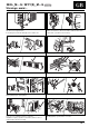
38GL_M…G / 38YY(S)_M…G R-410A Refrigerant connections No moisture. No dust. Charge liquid-no gas. No leak. No mineral oil. Copper tubes during storage. Neat. 1/2” UNF (R-410A) 7/16” UNF (R-22) Use tools designed for R-410A higher pressure. Keep inside clean. Dry nitrogen brazing. Min. – 100 kPa (– 755 mmHg) Vacuum. GB - 8 2-stage vacuum pump. Replace oil regularly.
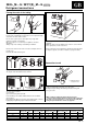
38GL_M…G / 38YY(S)_M…G R-410A Refrigerant connections ENGLISH Flaring the ends of the tubing Remove protective caps from copper tube ends. Position tube end downward, cut the tube to the requested length and remove the burrs with a reamer. Do not leave system open to atmosphere any longer than minimum required for installation. Oil in the compressor is extremely susceptible to moisture absorption. Always keep ends of tubing sealed during installation.
38GL_M…G / 38YY(S)_M…G R-410A Refrigerant connections 햸 햶 햹 햸 햷 햻 햻 햸 햹 햻 햵 햺 햻 햸 햹 햸 햳햲 햴 햹 햹 햴 햽 햲 햳 햴 햵 햶 햷 햸 햹 햺 햻 햽 햾 Three-way valve Needle valve Valve cap Valve needle Two-way valve Allen (hex. head) wrench Gas line (large diameter) Liquid line (small diameter) Flare nut Indoor unit Outdoor unit Vacuum pump 햾 Air drain Repeat the air drain procedure for every indoor unit installed. 헁 Use only a vacuum pump to purge air from the piping.
38GL_M…G / 38YY(S)_M…G R-410A Electrical connections ENGLISH Mod. 38GL2M12G A2 A1 쐃 L N NY 쐃 L N NY R C Y A2 230V ~ 50Hz L N R C Y A1 쐋 쐏 L N R C Y R C Y A1 A2 햲 쐇 햳햳 Mod. 38GL2M18G - 38GL2M24G B 쐃 L N NY A L N NY R C Y B 230V ~ 50Hz L N R C Y A 쐃 쐋 쐏 L N R C Y R C Y A B 햲 햳햳 쐇 WARNING! The system power supply must always be made through the outdoor unit. If the indoor units are provided with heaters, their power supply must be ensured by indoor sections.
38GL_M…G / 38YY(S)_M…G R-410A Electrical connections Mod. 38GL3M21G 쐃 A2 B L N N Y R C Y A2 L N N Y 쐃 A1 R C Y B L N N Y 230V ~ 50Hz L N R C Y A1 쐃 쐋 쐏 L N R C Y R C Y R C Y A1 A2 B 햲 햳햳 햳 쐇 Mod. 38GL4M24G A2 쐃 쐃 L N N Y R C Y R C Y A2 B1 A1 R C Y B2 햲 햳햳 햳 쐃 쐃 L N N Y 230V ~ 50Hz L N R C Y A1 B1 L N N Y B2 L N N Y 쐋 쐏 L N R C Y R C Y R C Y R C Y A1 A2 B1 B2 햳 쐇 WARNING! The system power supply must always be made through the outdoor unit.
38GL_M…G / 38YY(S)_M…G R-410A Electrical connections ENGLISH Mod. 38GL2M36G - 38GL2M48G L N R C Y L N R C Y A 햲 B 햳 햲 쐃 B R C Y 쐋 쐏 230V ~ 50Hz 230V ~ 50Hz A 햳 쐃 R C Y 쐋 쐏 L N R C Y A L N R C Y B 쐇 WARNING! The system power supply must always be made through the outdoor unit by means of two independent mains power supplies. If the indoor units are provided with heaters, their power supply must be ensured by indoor sections.
38GL_M…G / 38YY(S)_M…G R-410A Electrical connections Mod. 38YY2M18G - 38YY2M21G - 38YY2M24G R C Y O W2 R C Y O W2 L N A 햲 B 햳 쐃 A 쐃 L N N Y O W2 230V ~ 50Hz 햳 B L N N Y O W2 쐋 쐏 R C Y O W2 A L N R C Y O W2 B 쐇 WARNING! The system power supply must always be made through the outdoor unit. If the indoor units are provided with heaters, their power supply must be ensured by indoor sections.
38GL_M…G / 38YY(S)_M…G R-410A Electrical connections ENGLISH Mod. 38YY(S)2M36G - 38YY(S)2M48G L N R C Y O W2 L N R C Y O W2 A 햳햳 햲 쐃 쐃 R C Y O W2 S R C Y O W2 S 쐋 쐏 230V ~ 50Hz 230V ~ 50Hz 햲 B 쐋 쐇 L N R C Y O W2 A 햳햳 L N R C Y O W2 B PCB WARNING! The system power supply must always be made through the outdoor unit by means of two independent mains power supplies. If the indoor units are provided with heaters, their power supply must be ensured by indoor sections.
38GL_M…G / 38YY(S)_M…G Electrical connections and electrical data • Make electrical connections between units prior to proceeding to mains supply unit connection. • Before proceeding with the unit connection to the mains supply locate live L and neutral N, then make connections as shown in the wiring diagram. • Ensure that each mains supply connection has been made through a switch with contact gap of at least 3 mm.
38GL_M…G / 38YY(S)_M…G R-410A Pump Down and check the refrigerant charge ENGLISH Refrigerant charge control 38GL2M12G 38GL2M18G - 38GL2M24G - 38GL2M36G - 38GL2M48G 햾 헁 햽 햲 헂 햲 햻 햻 햷 햵 햳 햳 햺 햹 햶 햵 햷 햴 38GL3M21G 헂 햾 햶 햸 햽 햲 햻 햲 Outdoor unit Gas 햳 Circuit A compressor 햴 Circuit B compressor 햷 햴 햵 햸 햶 Liquid + Gas 햵 Outdoor unit coil 햶 Filter 햺 햷 Expansion device (Capillary) 햹 햹 Distributor Liquid 햸 Expansion device (Accurater) 햺 Solenoid valve 햻 Service valve 햽 Indoor
38GL_M…G / 38YY(S)_M…G R-410A Check the refrigerant charge Refrigerant charge control 38GL4M24G 햿 햾 햲 Outdoor unit 햳 Circuit A compressor 햴 Circuit B compressor 헀 햵 Outdoor unit coil 햽 햲 햶 Filter 햷 Expansion device (Capillary) 햸 Expansion device (Accurater) 햻 햹 Distributor 햺 Solenoid valve 햻 Service valve 햽 Indoor unit coil A1 햷 햴 햾 Indoor unit coil A2 햿 Indoor unit coil B1 햺 헀 Indoor unit coilB2 헁 Indoor unit coil A 헂 Indoor unit coil B 햹 햵 Gas Liquid + Gas 햳 햶 Liquid 햷 Heat pump unit
38GL_M…G / 38YY(S)_M…G R-410A Unit maintenance and troubleshooting Unit maintenance The following maintenance operations must be carried out by qualified personnel. Cleaning the coil When necessary, proceed as follows for more careful cleaning of the coil: Switch the mains supply OFF. Remove unit top cover by losening holding screws and lifting the cover. ENGLISH • Mains voltage wrong (too high or too low). • Condenser coil obstructed; remove obstructions. • Outdoor fan off; check cause and repair.
38GL_M…G / 38YY(S)_M…G R-410A Diagnostics The electronic control made on the unit ensures continuous monitoring of the unit operation and in case of wrong operation an alarm is generated. This alarm is signalled by the red LED (D6), which the electronic card is provided with. Moreover, an alarm log is stored into the electronic card memory, and it will be identified by a code. The memory contains a maximum of 6 alarms.
L010124H50 - 0303 Via R. Sanzio, 9 - 20058 Villasanta (MI) Italy - Tel. 039/3636.1 The manufacturer reserves the right to change any product specifications without notice. Order No. 13816-74M10, March 2003. Supersedes Order No. 13816-74M10, October 2002.