40 GKX INSTALLATION MANUAL
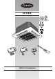
IR Remote Control “Room Controller” “Group Controller” “Zone Manager” The unit can be used with infrared Remote Control, with the Carrier “Room Controller” or “Group Controller” remote control. Some units can be used also with the Carrier “Zone Manager” remote control. Infrared control installation instructions are contained in this manual. Remote controls intallation instructions are contained in the relevant manuals.
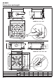
40 GKX Dimensions and weight 575 575 91 70 158 0 Ø Ø 15 225 280 298 120 52 56 720 40GKX 012 - 018 - 024 515 550 30 50 825 168 ø156 237 298 126 825 813 40GKX 028 - 036 - 048 - 060 66 GB - 2 kg 012 17.
0 GKX Technical data ENGLISH Table I: Nominal data POWER INPUT POWER INPUT Heat pump Cooling only Cooling (W) Heating (W) 75 75 Cooling (W) Heating (W) 75 – 40GKX012---703 40GKX018---703 80 – 40GKX018---703 80 80 40GKX024---703 105 – 40GKX024---703 105 105 40GKX028---703 108 – 40GKX028---703 108 108 40GKX036---703 140 – 40GKX036---703 140 140 40GKX048---703 185 – 40GKX048---703 185 185 40GKX060---703 230 – 40GKX060---703 230 230 40GKX112W--703 75 1575 4
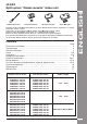
40 GKX General information Unit installation Read this instruction manual thoroughly before starting installation. • Inspect equipment for damage during transport. In case of damage file an immediate claim with the shipping company. Do not install or use damaged units. • This unit complies with the low-voltage (EEC/73/23) and electromagnetic compatibility (EEC/ 89/336) directives. • In case of malfunction turn the unit off, disconnect the mains power supply and contact a qualified service engineer.
40 GKX Avoid... ENGLISH ... any obstruction of the unit air intake or supply grilles. ... exposure to direct sunshine, when the unit is operating in the cooling mode; always use shutters or shades. ... positions too close to heating sources which may damage the unit. ... exposure to oil vapours. ... connecting condensate piping to sewage system drain without appropriate trap.
40 GKX Avoid... ... slack on electrical connections. ... disconnecting refrigerant connections after installation: this will cause refrigerant leaks. ... unnecessary turns and bends in connection pipes (see installation manual of outdoor unit). Excessive connection pipe length (see installation manual of outdoor unit). Installation Max.
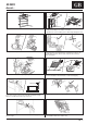
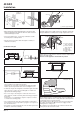
40 GKX Installation ENGLISH Prior to installation g g g Threaded hangers k "T" bar (to be removed) k It is advisable to place the unit as close as possible to the installation site before removing it from the packaging. The grille panel and the remote control are separately packed for maximum protection. First position the refrigerant lines, as described in the chapter “Refrigerant connections”. Remove the “T” bar in order to facilitate installation operations.
40 GKX Installation a Indoors b Outdoors a Frame support brackets Making the hole for connection pipes in the external wall Installation of grille/frame assembly • After positioning the units and determining the connection position, make a 70 mm Ø hole in the wall. The same hole can be used as a condensate drain pipe conduit. Carefully unpack the assembly and check for damage sustained in transport. Attach the assembly to the unit by using the two hooks.
40 GKX Refrigerant connections ENGLISH IMPORTANT: During the unit installation make first refrigerant connections and then electrical connections. If unit is uninstalled first disconnect electrical cables, then refrigerant connections. Refer to the outdoor unit installation manual for tube sizing, and limitations (slope, length, number of curves allowed, refrigerant charge, etc.). Pipe connection to the unit Use two wrenches to tighten all connections.
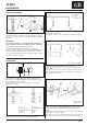
40 GKX Electrical connections CV CLR CA C b C h c CP CP a d CV CG f CP R C W2 O Y S2 S1 a i e CLR f i CA g c g b A A h B B e CONTROL PANEL mod. 12 - 18 - 24 a b c d e Condenser Ground connection screws Internec board Auxiliary board Outdoor unit connection terminal board d CONTROL PANEL mod.
40 GKX Electrical connections ENGLISH Cooling only mod. 12 - 18 - 24 E mod. 28 - 36 - 48 - 60 Heat pump A B mod. 12 - 18 - 24 mod. 12 - 18 - 24 mod. 28 - 36 - 48 - 60 mod. 28 - 36 - 48 - 60 Terminal box legend, all models a Interconnecting wire, indoor-outdoor units (field wiring).
40 GKX Wiring diagram - Cooling only or heat pump units T BUTTON BOARD R R R J4 TM AIR J6 COIL J3 A SEC SWG-LVR J1 LED-BRD J5 TM COIL R R B 1 AIR A R J12 IR-CONN PRIM P3 OD COIL J10 BUTTON BRD P2 Y G B J7 FS MAIN BOARD J2 AUX BRD 9 1 W W G COMP ODRFAN LED-I.R.
40 GKX Wiring diagram - Cooling only or heat pump units with electric heater ENGLISH T BUTTON BOARD R R R J4 TM AIR R R A R B J12 IR-CONN J6 1 SEC SWG-LVR AIR PRIM P3 A J1 LED-BRD J5 TM COIL COIL J3 BUTTON BRD OD COIL J10 P2 Y J8 Y 8 J7 G * 1 MSL G G ODRFAN RVS COMP C W B B C4 G J9 1 B LM * IDR/FAN 6 1 LED-I.R.
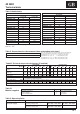
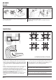
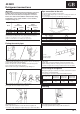
40 GKX Fresh air renewal and conditioned air supply to an adjacent room 105 120 f 49 B ØA 70 a 216 e g b d g h i a b c d e f c Model ØA B 12 ÷ 24 150 120 28 ÷ 60 156 126 Duct connection flange Clip 6 mm neoprene gasket Insulated flexible duct Fresh air intake Conditioned air supply to an adjacent room g Polystyrene partition h Baffle i Frame Air intake grille j j Wall k Undercut door l Wall-fitted grille m Door-fitted grille k • Side knockouts allow connection of fresh air inlet duct
40 GKX Fresh air renewal and conditioned air supply to an adjacent room ENGLISH Diagram of conditioned air supply to an adjacent room: one louvre closed External static pressure - Pa 40 30 20 24/28 60 36 10 12 18 48 0 0 100 300 200 410 400 450 3 Air flow m /h ➀ Supply air duct to adjacent room In case of two louvres closed, the fresh air flow towards the adjacent room is 50% higher compared with only one louvre closed (with equal static external pressure).
40 GKX Control configuration and operating test Remote control configuration Once the electrical connections have been completed, enter the system configuration. Check the correct positioning of the switch (see “Electrical connections”). Incorrect switch positioning will cause serious damage to the system. Remote control configuration with cable connection has to be made following the instructions contained in the respective manuals.
40 GKX Maintenance ENGLISH Maintenance Additional maintenance Cleaning and maintenance operations must be carried out by specially trained personnel. • The electric panel is easily accessible by removing the cover panel. The inspection or replacement of internal components such as: fan motor, coil, condensate discharge pump, float switch, coil sensors, electric heater (if fitted), involve the removal of the condensate drain pan.