
Installation manual
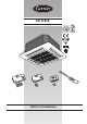

GB - 7
40 GKX
ENGLISH
Prior to installation
It is advisable to place the unit as close as possible to the
installation site before removing it from the packaging. The grille
panel and the remote control are separately packed for maximum
protection.
IMPORTANT:
Do not lift the unit by the condensate drain discharge pipe or
by the refrigerant connections; hold it by its four corners only.
Unit installation will be facilitated using a stacker.
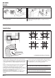
If plaster board ceiling panels are installed the maximum
dimensions of the unit housing must not exceed 660 x 660 mm (for
models 12-18-24) and 900 x 900 mm (for models 28-36-48-60).
In rooms with high humidity, brackets should be insulated using the
self adhesive insulation supplied.
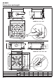
Installation
Installation
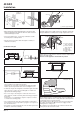
a
d
b
c
d
a
g g
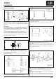
m False ceiling
n Spirit level
m n n
e
f
g
h
i
j
k
g g
l l
kk
l
l
k
mm
Align and level the unit by adjusting the nuts and locknuts on
the threaded hangers, maintaining a distance of 25 - 30 mm
between the sheet metal body and the underside of the false
ceiling.
Reposition the “T” bar and align the unit in relation to the bar by
tightening the nuts and locknuts.
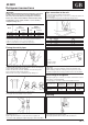
After connection of the condensate drain line and the refrigerant
lines, carry out a final check to make sure that the unit is level.
Carefully lift the unit (without the frame) using the four
suspension brackets (or the four corners), inserting it into the
false ceiling.
If the “T” bar cannot be removed the unit may need to be tilted
(this operation may only be carried out with false ceilings with a
minimum height of 300 mm).
First position the refrigerant lines, as described in the chapter
“Refrigerant connections”.
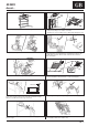
Remove the “T” bar in order to facilitate installation operations.
Mark the position of the hangers, refrigerant lines and condensate
drain pipe, power supply cables and remote control cable (see
dimensions); the cardboard template (supplied with the kit) may
be of assistance for this operation.
Depending on the type of ceiling the hangers can be fixed as
shown in the drawing.
Once the threaded hangers have been positioned, do not tighten
the nuts, and insert the washers as shown in the drawing.
f Washer
g Threaded hangers
h Washer
i Nut
j Nut
a Nut
b Wooden frame
c Threaded hangers
d Washers
e Nut
g Threaded
hangers
k "T" bar
(to be removed)
l Suspension brackets