Container Refrigeration Unit Models 69NT40-511-1 to 69NT40-511-199 and 69NT40-521 DUE TO THE LARGE NUMBER OF SCHEMATIC DIAGRAMS CONTAINED IN THIS BOOK, THE BOOK IS PRESENTED AS TWO FILES.
OPERATION AND SERVICE MANUAL CONTAINER REFRIGERATION UNIT MODELS 69NT40-511-1 to 69NT40-511-199 and 69NT40-521 Carrier Transicold Division, Carrier Corporation, P.O. Box 4805, Syracuse, N.Y. 13221 E Carrier Corporation 1999 S Printed in U. S. A.
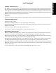
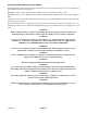
GENERAL SAFETY NOTICES The following general safety notices supplement the specific warnings and cautions appearing elsewhere in this manual. They are recommended precautions that must be understood and applied during operation and maintenance of the equipment covered herein. The general safety notices are presented in the following three sections labeled: First Aid, Operating Precautions and Maintenance Precautions.
SPECIFIC WARNING AND CAUTION STATEMENTS To help identify the label hazards on the Unit and explain the level of awareness each one carries, an explanation is given with the appropriate consequences: DANGER -- means an immediate hazard which WILL result in severe personal injury or death. WARNING -- means to warn against hazards or unsafe conditions which COULD result in severe personal injury or death.
TABLE OF CONTENTS Section Page SAFETY SUMMARY . . . . . . . . . . . . . . . . . . . . . . . . . . . . . . . . . . . . . . . . . . . . . . . . . . . . . . Safety-1 GENERAL SAFETY NOTICES . . . . . . . . . . . . . . . . . . . . . . . . . . . . . . . . . . . . . . . . . . . . . . Safety-1 FIRST AID . . . . . . . . . . . . . . . . . . . . . . . . . . . . . . . . . . . . . . . . . . . . . . . . . . . . . . . . . . . . . . . Safety-1 OPERATING PRECAUTIONS . . . . . . . . . . . . . . . . . . . . . . . . . . . .
TABLE OF CONTENTS (CONTINUED) Section Page 3.3.1 Brief Description . . . . . . . . . . . . . . . . . . . . . . . . . . . . . . . . . . . . . . . . . . . . 3-24 3.3.2 DataCORDER Configuration . . . . . . . . . . . . . . . . . . . . . . . . . . . . . . . . . 3-25 3.3.3 DataCORDER Function Codes . . . . . . . . . . . . . . . . . . . . . . . . . . . . . . . 3-26 3.3.4 DataCORDER Alarms . . . . . . . . . . . . . . . . . . . . . . . . . . . . . . . . . . . . . . . 3-27 3.3.
TABLE OF CONTENTS (CONTINUED) Page SERVICE . . . . . . . . . . . . . . . . . . . . . . . . . . . . . . . . . . . . . . . . . . . . . . . . . . . . . . . . . . . . . . . . 6.1 MANIFOLD GAUGE SET . . . . . . . . . . . . . . . . . . . . . . . . . . . . . . . . . . . . . . . . . . . . 6-1 6-1 6.2 6.3 SUCTION AND DISCHARGE SERVICE VALVES . . . . . . . . . . . . . . . . . . . . . . . PUMPING THE UNIT DOWN . . . . . . . . . . . . . . . . . . . . . . . . . . . . . . . . . . . . . . . . 6-4 6-4 6.4 6.
TABLE OF CONTENTS (CONTINUED) Section Page 6.26 THERMOSTATIC EXPANSION VALVE . . . . . . . . . . . . . . . . . . . . . . . . . . . . . . . . 6-26 6.27 CONTROLLER/DATACORDER . . . . . . . . . . . . . . . . . . . . . . . . . . . . . . . . . . . . . . 6-28 6.27.1 Controller/DataCORDER Programming Procedure . . . . . . . . . . . . . . 6-29 6.27.2 Controller Trouble-Shooting . . . . . . . . . . . . . . . . . . . . . . . . . . . . . . . . . . 6-29 6.28 WATER-COOLED CONDENSER . . . . . . . . . . . .
LIST OF ILLUSTRATIONS (CONTINUED) Page Figure 6-1 Manifold Gauge Set . . . . . . . . . . . . . . . . . . . . . . . . . . . . . . . . . . . . . . . . . . . . 6-1 Figure 6-2 R-134a Manifold Gauge Set Connection . . . . . . . . . . . . . . . . . . . . . . . . . . 6-3 Figure 6-3 Suction or Discharge Service Valve . . . . . . . . . . . . . . . . . . . . . . . . . . . . . . 6-4 Figure 6-4 Vacuum Pump Connections . . . . . . . . . . . . . . . . . . . . . . . . . . . . . . . . . . . . .
LIST OF TABLES Table Page Table 1-1 Model Chart . . . . . . . . . . . . . . . . . . . . . . . . . . . . . . . . . . . . . . . . . . . . . . . . . . . 1-2 Table 2-1 Safety and Protective Devices . . . . . . . . . . . . . . . . . . . . . . . . . . . . . . . . . . . 2-19 Table 3-1 Controller Configuration Variables . . . . . . . . . . . . . . . . . . . . . . . . . . . . . . . . 3-3 Table 3-2 Key Pad Function . . . . . . . . . . . . . . . . . . . . . . . . . . . . . . . . . . . . . . . . . . . . . .
SECTION 1 INTRODUCTION 1.1 INTRODUCTION The temperature Controller/DataCORDER (Micro-Link 2i) is a microprocessor-based controller and a integrated electronic data logging device. Refer to sections 3.1 and 3.3. Once the temperature controller is set at a desired container temperature, the unit will operate automatically to maintain the desired temperature within very close limits.
Two-Sp Speed Compr pressor Water-C r-Cooled Conden enser 2 Row 4 Row Suction & Discharge Pressure O Option Humidity ty Sensor Trans nsFresh Communiccations Interface M Module (CI) Partlow Tem emperature Recorder Saginoomiya Tempeerature Record rder 69NT40 511 2 69NT40-511-2 Transsformer 69NT40 511 1 69NT40-511-1 NT0001 X P X P X --- --- X --- X X --- NT0062 X P X P X --- --- X --- X X --- NT0002 X P X X X --- --- X --- X X --- PID USDA AC Cold Treatm ment
Water-Cooled Condenser 2 Row 4 Row Suction & Discharge Pressure Option Humidity Sensor TransFresh Communications Interface Module (CI) Partlow Temperature Recorder Saginomiya Temperature Recorder P X --- P X --- A P --- X X --- 69NT40-511-19 NT0037 P X --- P X --- --- P --- --- X --- 69NT40-511-21 NT0055 P X --- P X --- --- P X --- X --- NT0046 P X --- P --- X A P --- --- X --- NT0121 P X --- P --- X A P --- --- X --- NT0139 P X -
Two-Speed Compressor Water-Cooled Condenser 2 Row 4 Row Suction & Discharge Pressure Option Humidity Sensor TransFresh Communications Interface Module (CI) Partlow Temperature Recorder Saginomiya Temperature Recorder Condenser Coil Transformer NT0074 X --- --- --- --- X A X --- X --- --- NT0135 X --- --- --- --- X A X --- X --- --- Figure 7-11 & Figure 7-12 NT0208 X --- --- --- --- X A X --- X --- --- NT0246 X --- --- --- --- X A X --- X --- --
Two-Speed Compressor Water-Cooled Condenser 2 Row 4 Row Suction & Discharge Pressure Option Humidity Sensor TransFresh Communications Interface Module (CI) Partlow Temperature Recorder Saginomiya Temperature Recorder P P --- P X --- --- P --- P X --- NT0134 P P --- P X --- --- P --- P X --- Figure 7-9 & Figure 7-10 NT0184 P P --- P X --- --- P --- P X --- NT0216 P P --- P X --- --- P --- P X --- NT0268 P P --- P X --- --- P --- P X --
69NT40-511-65 TransFresh Communications Interface Module (CI) Partlow Temperature Recorder Saginomiya Temperature Recorder Condenser Coil Humidity Sensor 69NT40-511-64 Suction & Discharge Pressure Option 69NT40 511 63 69NT40-511-63 4 Row 69NT40-511-62 2 Row 69NT40 511 61 69NT40-511-61 Water-Cooled Condenser 69NT40 511 60 69NT40-511-60 Two-Speed Compressor 69NT40-511-59 Transformer 69NT40 511 58 69NT40-511-58 NT0105 P X --- P X --- --- P --- P X --- NT0122 P X --- P X -
Water-Cooled Condenser 2 Row 4 Row Suction & Discharge Pressure Option Humidity Sensor TransFresh Communications Interface Module (CI) Partlow Temperature Recorder Saginomiya Temperature Recorder X --- P X --- --- P X P X --- NT0235 P X --- P X --- --- P X P X --- NT0157 P X --- P X --- --- P X P X --- NT0200 P X --- --- X --- --- P X P X --- NT0158 P P --- P --- X --- P --- P X --- NT0159 P P --- P X --- --- P --- P X ---
Two-Speed Compressor Water-Cooled Condenser 2 Row 4 Row Suction & Discharge Pressure Option Humidity Sensor TransFresh Communications Interface Module (CI) Partlow Temperature Recorder Saginomiya Temperature Recorder Condenser Coil Transformer P P --- P X --- --- P --- P X --- NT0202 --- --- --- P --- X --- P --- P --- --- NT0238 --- --- --- P --- X --- P --- P --- --- NT0278 --- --- --- P --- X --- P --- P --- --- NT0318 --- --- --- X ---
Two-Speed Compressor Water-Cooled Condenser 2 Row 4 Row Suction & Discharge Pressure Option Humidity Sensor TransFresh Communications Interface Module (CI) Partlow Temperature Recorder Saginomiya Temperature Recorder P X --- P --- X A X X P X --- NT0277 P X --- P --- X A X X P X --- Figure 7-49 & Figure 7-50 NT0315 P X --- P --- X A X X P X --- NT0354 P X --- P --- X A X X P X --- NT0381 P X --- P --- X X X X P X --- NT0385 P X --
SECTION 2 DESCRIPTION 2.1 GENERAL DESCRIPTION allow front entry into the evaporator section, and the center access panel allows access to the thermostatic expansion valve and evaporator coil heaters. The unit model number, serial number and parts identification number will be found on the front of the unit to the left of the compressor. a. Refrigeration Unit -- Front Section The front section of the refrigeration unit shows access to most parts of the unit (i.e., compressor, condenser, receiver, etc.
b. Evaporator Section When transporting perishable (chilled) commodities, the fan motors will normally be in high speed above --10_C (+14_F), or --5_C (+23_F) optionally.
4 3 8 7 5 2 1 9 19 10 18 6 17 16 15 11 SECTION 2 14 12 13 1. 2. 3. 4. 5. 6. Evaporator Fan Motor #1 (EM1) Humidity Sensor (HS) -- Optional Return Recorder Sensor (RRS) Return Temperature Sensor (RTS) Mechanical Recording Thermometer Bulb Mechanical Recording Thermometer Bulb -Used on PID NT0073 7. Evaporator Fan Motor #2 (EM2) 8. Defrost Termination Sensor (DTS) 9. Heater Termination Thermostat (HTT) 10. 11. 12. 13. 14. 15. 16. 17. 18. 19.
c. Compressor Section the left of the compressor. The compressor section includes the compressor, power cable storage compartment, and an optional transformer (refer to Table 1-1 and Figure 2-9), which is located to This section also contains the discharge/suction pressure transducers. optional 1 2 3 10 11 9 4 8 5 6 7 1. 2. 3. 4. 5. 6.
d. Condenser Section When the unit is operating, air is pulled in the bottom of the coil and discharged horizontally out through the front of the condenser fan grille. The condensing section consists of a condenser fan motor, a condenser fan and an air-cooled condenser coil. 7 8 6 1 SECTION 2 5 3 4 2 2 1. 2. 3. 4. Grille and Venturi Assembly Retaining Screw Condenser Fan Key 5. Condenser Fan Motor (CM) 6. Condenser Coil Cover 7. Condenser Coil 8. Condenser Motor Mount Bracket Figure 2-4.
e. Receiver Section discharge pressure regulator valve. The receiver section consists of quench expansion valve, manual liquid line valve, filter-drier, receiver with sight glass/moisture-liquid indicator, condenser pressure transducer (CPT), fusible plug, suction modulation valve, suction solenoid valve, and The supply temperature sensor (STS), supply recorder sensor (SRS) and ambient sensor (AMBS) are located at the right side of the compressor.
f. Water-Cooled Condenser Section (Optional) discharge pressure regulator valve, water hook-up couplings and water pressure switch.
g. Control Box with a Single-Speed Compressor Controller/DataCORDER module (See Figure 2-7), an optional remote monitoring unit (CI), and an optional emergency bypass cooling switch (EB), emergency defrost switch (ED) and emergency defrost fuse (FED). The control box includes the manual switches, circuit breaker(s), contactors, transformer, fuses, key pad, display module, current sensor module, 1 22 1. 2. 3. 4. 5. 6. 7. 8. 9. 10. 11. 12.
h. Control Box with a Two-Speed Compressor (Optional) display module, current sensor module, Controller/DataCORDER module (See Figure 2-8), and an optional remote monitoring unit (CI). The control box includes the manual switches, circuit breaker(s), contactors, transformer, fuses, key pad, 1 2 3 4 5 6 7 8 SECTION 2 CAUTION: DO NOT MANUALLY ENGAGE CONTACTORS 18 1. 2. 3. 4. 5. 6. 7. 8. 9.
2.2 REFRIGERATION SYSTEM DATA Number of Cylinders Model CFM i. Compressor/Motor Assembly Weight (Dry) Approved Oil Oil Charge Oil Sight Glass Verify at --18 _C (0 _F) container box temperature Opens k Heater Termination Thermostat k. Closes Cutout l High Pressure Switch l. Cut-In j. Expansion Valve Superheat Unit Configuration m. Refrigerant Charge 6 06DR 41 118 kg (260 lb) - Single-Speed 129.39 kg (285.25 lb) - Two-Speed Castrol Icematic -- SW20 3.6 liters (7.6 U.S.
Full Load Amps Horsepower c. Condenser C d Fan F Rotations Per Minute Motor Voltage and Frequency Bearing Lubrication Rotation Number of Heaters Rating d Drain Pan Heaters d. Resistance (cold) Type Number of Heaters Rating e. E Evaporator t C Coil il Resistance (cold) Heaters Ambient Type Full Load Amps -- High Speed Full Load Amps -- Low Speed Nominal Horsepower -High Speed Nominal Horsepower -Low Speed f.
i. Humidity Sensor ((HS)) -- Optional p Orange wire Power Red wire Output Brown wire Ground Input voltage 5 vdc Output voltage 0 to 3.3 vdc Output voltage readings verses relative humidity (RH) percentage: 30% 0.99 V 50% 1.65 V 70% 2.31 V 90% 2.97 V 2.4 POWER AUTOTRANSFORMER (Optional) 2. Plug the 230 vac (black) cable into a de-energized 190/230 vac, 3-phase power source. Energize the power source. Set circuit breaker (CB-2 if equipped) to position “1” (ON).
2.5 UPPER FRESH AIR MAKEUP VENT arrow on the disc with the percentage of desired air flow marked on the supplied label (see Figure 2-1). The purpose of the fresh air makeup vent is to provide ventilation for commodities that require fresh air circulation. The vent must be closed when transporting frozen foods or controlled atmosphere loads. 2.
2.7 REFRIGERATION CIRCUIT WITH RECEIVER superheat at the coil outlet regardless of load conditions, except at abnormally high container temperatures such as during pulldown (valve at maximum operating pressure condition). Starting at the compressor, the suction gas is compressed to a higher temperature and pressure. When operating with the air-cooled condenser, the gas flows through the discharge service valve into the pressure regulator valve that is normally open.
6 7 8 5 9 3 4 17 19 2 11 16 12 18 13 1 15 1. 2. 3. 4. 5. 6. 7. 8. 9. 10. Suction Service Valve Discharge Service Valve Discharge Pressure Regulator Valve Air-Cooled Condenser Evaporator Thermostatic Expansion Valve External Equalizer Line Thermostatic Expansion Valve Bulb Heat Exchanger Fusible Plug (Located on back of receiver) 14 11. Sightglass 12. Condenser Pressure Transducer (CPT) (Located on the back-side of the receiver) 13. Sight Glass/Moisture Indicator 14.
2.8 REFRIGERATION CIRCUIT WITH THE WATER-COOLED CONDENSER (Optional) b. Maintain a flow rate of 11 to 26 liters per minute (3 to 7 gallons per minute). The water pressure switch will open to de-energize the condenser fan relay. The condenser fan motor will stop and will remain stopped until the water pressure switch closes. Starting at the compressor, the suction gas is compressed to a higher temperature and pressure.
6 7 8 5 9 11 10 3 4 2 12 18 16 19 17 15 14 1 1. 2. 3. 4. 5. 6. 7. 8. 9. 10. Suction Service Valve Discharge Service Valve Discharge Pressure Regulator Valve Air-Cooled Condenser Evaporator Thermostatic Expansion Valve External Equalizer Line Thermostatic Expansion Valve Bulb Heat Exchanger Rupture Disc 11. 12. 13. 14. 15. 16. 17. 18. 19.
2.10 SUCTION SOLENOID VALVE 2.11 REMOTE MONITORING (Optional) The suction solenoid valve, shown in Figure 2-5, is controlled by the Controller relay (TS). NOTE The in-range light will be illuminated if the container control air temperature is within the tolerance selected. Refer to section 3.1.4 (Code 30). a.
2.12 SAFETY AND PROTECTIVE DEVICES IP-CP or HPS will shut down the compressor. Unit components are protected from damage by safety and protective devices listed in Table 2-1. These devices monitor the unit operating conditions and open a set of electrical contacts when an unsafe condition occurs. Open safety switch contacts on device IP-CM will shut down the condenser fan motor.
SECTION 3 MICROPROCESSOR 3.1 MICRO-LINK 2i CONTROLLER MODULE 1 2 8 1. 2. 3. 4. 2 3 4 2 5 2 2 6 7 Micro-Link 2i Controller/DataCORDER Module Connectors Test Points Fuses 5. Control Circuit Power Connection (Location: In back of connector) 6. Battery Pack (Optional) 7. Software Programming Port 8. Mounting Screw 3.1.1 Brief Description The Carrier Transicold Micro-Link 2i Controller/DataCORDER is a custom-designed microprocessor-based module which incorporates embedded software to: a.
f. Provide reprogrammability and configuration through a memory card. The memory card automatically downloads new software to the Controller when inserted, and controls output to the display for status information. Operational Software: This software operates the Controller module, which turns fans on and off, turns the compressor on and off, etc. Configuration Software: g. Provide electronic data storage.
Table 3-1.
3.1.3 General Layout of the Controller Section Table 3-2. Key Pad Function The Micro-Link 2i Controller/DataCORDER consists of a key pad, display module and Controller module. Connectors are used to attach the wiring of the unit to the Controller module. The Controller module is designed to permit ease of installation and removal. All control functions are accessed by key pad selections and viewed on the display module which are designed for optimum user friendliness and convenience.
The display module (see Figure 3-2) is mounted at a 20 degree downward tilt to aid in visibility. The display module consists of: a. Two 25mm (1 inch) high, five digit LCD displays which are easily viewed in direct sunlight and backlighted for superior low-light visibility. b. Seven Indicators: S Cool -- White Lamp: Energized when the refrigerant compressor is energized. S Heat -- Orange LED: Energized when the heaters are on, and the unit is in the heat or defrost mode.
3.1.4 Controller Function Codes (see Table 3-3). For the display only function codes, the right window will display the value of this item for five seconds before returning to the normal display mode. If a longer time is desired, pressing the ENTER key will extend the time to 30 seconds after the last pressing of the ENTER key. Function codes are explained in Table 3-3. There are thirty-nine functions which the operator may access to examine the operating status of the unit.
CODE # TITLE DESCRIPTION Inapplicable Functions Display ---------Condenser pressure is displayed using a pressure transducer. Pressure is displayed in units of psig when code 28 is set to _F and units of bars when Condenser Pressure function code Cd28 is set to _C. “P” is displayed after the value to indicate psig, Cd13 (CPC) “b” appears after the value to indicate bars and “i” appears after the value for inches of mercury.
CODE # TITLE DESCRIPTION Inapplicable Functions Display ---------Display Only Functions NOTE Function codes Cd27 through Cd37 are user-selectable functions. The operator can change the value of these functions to meet the operational needs of the container. Cd27 Defrost Interval (Hours) The defrost interval is the time interval between defrost cycles. Five selectable values are available: 3, 6, 9, 12 or 24 hours. The factory default value is 12 hours.
TITLE DESCRIPTION Inapplicable Functions Display ---------The current limit is the maximum current demand allowed on any phase at any time. Limiting the unit’s current (amperage) reduces the load on the main power and lowers the compressor discharge pressure. When desirable, the limit can be Current Limit Cd32 lowered. Note, however, that capacity is also reduced.
CODE # TITLE Secondary Return Cd39 Air Temperature (Optional) 3.1.5 DESCRIPTION Inapplicable Functions Display ---------This code is only applicable to units without a DataCORDER, that are configured to have four probes. If this is true, it will then display the current secondary return air temperature.If the unit is configured with a DataCORDER, the Controller function code Cd39 will display “----------,” and the display values for RRS will appear on the DataCORDER function code dC2.
Table 3-4.
CODE # AL53 TITLE NiCad Battery Pack Failure DESCRIPTION Alarm 53 is caused by the nicad battery pack being too low of a charge for battery-backed recording. NOTE Check for recharging or replacing battery pack. Primary Supply Air AL54 Sensor Failure (STS) Alarm 54 is activated by an invalid primary supply sensor reading that is sensed outside the range of --50 to +70_C (--58_F to +158_F) or if the probe check logic has determined there is a fault with this sensor.
CODE # TITLE DESCRIPTION Alarm 63 is triggered by the current limiting system. If the compressor is ON and current limiting procedures cannot maintain a current level below the user selected limit, the current limit alarm is activated.This alarm is a display alarm and AL63 Current Over Limit is inactivated by power cycling the unit, changing the current limit via the code select Cd32, or if the suction modulation valve (SMV) is allowed to open to 100% and the suction solenoid valve is allowed to open.
3.1.6 Condenser Pressure Control (CPC) The Controller configuration variable for “Heat Lockout” (refer to Table 3-1) can be changed for set points of either --10_C (+14_F), or --5_C (+23_F) optionally. A pressure control system has been incorporated by means of a condenser pressure transducer (CPT) and condenser pressure control (CPC) logic to maintain discharge pressures above 130 psig in low temperatures.
modulation valve (SMV) and suction solenoid valve (SSV) with the compressor energized. 3. The control probe (i.e.; Supply 1) temperature is less than set point, plus 0.25_C. When pulling down from a control temperature that is more than 5_C (9_F) above set point, both valves will be open to reduce the pulldown time unless suction solenoid override or current limiting is activated. See section 2.10 for explanation of suction solenoid override.
out-of-range or compressor shutdown condition, the heat relay is de-energized immediately. minutes and the above mentioned cycle will be repeated, just as it was from the start of the cooling or heating cycle. If the unit is not equipped with dual speed evaporator fans, then economy mode perishable will perform exactly the same as the normal control mode. The out-of-range timer is provided to allow the heaters to remain energized during a temporary out-of-range condition.
3.1.7.2 Frozen Range Below --10_C (+14_F), or --5_C (+23_F) Optionally excluding the Controller, will be turned off when the control temperature is less than or equal to the set point -2_C, (i.e., the set point is set at --11_C and the operator subtracts --2_C, the result will equal --13_C). After an off-cycle period of 60 minutes, the unit will turn on high speed evaporator fans for three minutes, and then check the control temperature.
the VENT mode is selected on the CA Controller. The user must scroll through the selection by pressing the UP ARROW or DOWN ARROW keys, then pressing the ENTER key when the selection is made. While the tests are being executed, the user can terminate the pre-trip mode by holding the PRE-TRIP key. The unit will then resume normal operation. If the user decides to terminate a test but remain at the test selection menu, the user may press the UP ARROW key.
c. Auto Test Operation From Serial Communications d. Pre-Trip Test Results Pre-trip may also be initiated via communications. The operation is the same as for the Auto Test mode described above except that should a test fail, the pre-trip mode will automatically terminate. When initiated via communications, a test may not be interrupted with an arrow key, but the pre-trip mode can be terminated with the PRE-TRIP key.
CODE # P4-1 P5-0 P5-1 TITLE DESCRIPTION Setup: The high speed Evaporator Fan is turned off, a current draw test is done after 10 seconds. Pass/Fail Criteria: Passes if change in current draw is within the range specified. Fails if AL11 or AL12 activates during test. Setup: The High Speed Evaporator Fan is turned on and run for eight minutes, with all other outputs de-energized. Pass/Fail Criteria: A temperature comparison is made between the return and Supply/Return Probe supply probes.
TITLE P6-H High Speed Compressor Tests (F dual (For d l speed d units) P6-L Low Speed Compressor Tests (F dual (For d l speed d units) P6-2 Suction Modulation Valve (Open) P6-3 Quench Valve Test P6-4 Suction Modulation Valve (Closed) P6-5 Suction Solenoid Valve DESCRIPTION Setup: The compressor is started.
CODE # TITLE DESCRIPTION NOTE Starting with test P7-0 through test P10, these tests are only included with the “Auto2” (Optional) selection menu. (Refer to section 3.2.1.) Setup: When the unit is running, the condenser fan is de-energized, and a 15 minute timer is started.
TITLE P8-1 Perishable Mode Pull Down Test P8-2 Perishable Mode Maintain Temperature Test P9-0 Defrost Test P10-0 Frozen Mode (Setup) Test DESCRIPTION Requirements: Control temperature must be at least 60_F. Setup: The set point is changed to 32_F, and a 180 minute timer is started. The left display will read “P8-1,” the right display will show the supply air temperature. The unit will then start to pull down the container temperature to the 32_F set point.
CODE # P10-1 TITLE Frozen Mode (Pull Down) Test Frozen Mode P10-2 Maintain Temperature Test DESCRIPTION Setup: When the container temperature is greater than or equal to the 45_F. set point which was set in the frozen mode heat test, the left display will read “P101” and the right display will show the return air temperature. The set point will then be changed to --17.7_C (0_F). The unit will then have a maximum of three hours to pull the container temperature down to the 0_F set point.
S S S S S S S S S S S S S S S S 3.3.
3.3.3 DataCORDER Function Codes until the left window displays the desired code number (see Table 3-6). The right window will display the value of this item for five seconds before returning to the normal display mode. If a longer time is desired, pressing the ENTER key will extend the time to 30 seconds after the last pressing of the ENTER key. There are 35 functions which the operator may access to examine the operating status of the unit.
3.3.4 DataCORDER Alarms S To Display Alarm Codes: While in Set Point Selection or Default Display mode, press the ALT. MODE & ALARM LIST keys. This accesses the Alarm List Display Mode, which displays any alarms stored in the Alarm Queue. The user may scroll to the end of the alarm list by pressing the UP ARROW key after the ALARM LIST key is depressed. Depressing the DOWN ARROW key allows the user to scroll backward in the alarm list.
Table 3-7. DataCORDER Alarm Indications To Access: Press ALT.
The DataCORDER alarms for the USDA and cargo probes are configurable using the interrogation program or via a configuration card. There are four configuration variables for the DataCORDER, which are listed in Table 3-8 with their descriptions and selection values. The DataCORDER may be powered up in several ways: 1. Normal AC power: The DataCORDER is powered up when the unit is turned on via the stop-start switch (ST). 2.
e. Display vs. Configuration Codes Standard Mode: The DataCORDER contains two types of display codes; Display and Configuration. Display codes will display parameter values, but will not let them be modified. Configuration codes can be modified via the interrogator or with the insertion of the common configuration software card. The standard recording mode allows the user to configure the DataCORDER to monitor data using one of seven standard configurations.
Right Display: Or: #3 probes (and possibly the optional Cargo probe) are installed in their receptacles. “dALnn” where nn = the alarm history entry 01-08 “xA nn” where x = “I” (inactive) or “A” (active) “----------” if no alarms are currently in the alarm history list The DataCORDER records up to six probe temperatures (supply, return, USDA #1, #2, #3 and an optional cargo probe #4), at the logging interval. The standard DataCORDER report displays the supply and return air temperatures.
Start, Power Outages, and Temperature Out-of-Range conditions. b. Pre-cool to treatment temperature. c. Install the DataCORDER module battery pack (if not already installed). 3.3.10 DataCORDER Scrollback d. Calibrate the three USDA probes by ice bathing the probes and performing the calibration function with the hand held DataReader or a DOS-based portable computer. This calibration procedure determines the probe offsets and stores them in the Controller for use in generating the cold treatment report.
Table 3-10. DataCORDER Pre-Trip Data TEST # TITLE DATA NOTE “Auto” or “Auto1” menu includes the following: P, P1, P2, P3, P4, P5, P6 and rSLts. “Auto2’ (Optional) menu includes the following: P, P1, P2, P3, P4, P5, P6,P7, P8, P9, P10 and rSLts. (Refer to section 3.2.1.
CONTAINER ABCDXXXXXXX ON 08Jul 94 FROM 15Apr94 TO 17Apr94 (DEGREES C) PAGE: 1 HEADER INFORMATION DataCorder SN: XXXXXXXX ALARMS REPORT ALARM NUM FIRST ACTIVE LAST ACTIVE CONTROLLER ALARMS: 60 17Apr94 03:28 DATACORDER ALARMS 17Apr94 16:13 No Alarms Reported DATE: 15Apr94 23:49 Trip Start USDA SUMMARY LEGEND SP PS, PE NEW SN dal NEW SW Setpoint Change Pretrip Start/End Controller Rep.
FALLING TEMPERATURE RISING TEMPERATURE +1.5_C (2.7_F) COOLING +1_C (1.8_F) COOLING +0.5_C (0.9_F) +.20_C SET POINT --0.20_C --0.5_C (0.9_F) AIR CIRCULATION ONLY --1_C (1.8_F) AIR CIRCULATION ONLY --1.5_C (2.7_F) NOTE For In-range Tolerance, Refer to section 3.1.4 Code 30. Figure 3-4. Controller Set Point BELOW --10_C (+14_F), or --5_C (+23_F) optionally FALLING TEMPERATURE RISING TEMPERATURE MODULATING COOLING * +1_C (1.8_F) SECTION 3 +1.5_C (2.7_F) MODULATING COOLING * +0.5_C (0.9_F) +.
STEP * Compressor Starting Sequence A ** Required voltage is a function of operating capacity and supply frequency. NO Is Ambient Temperature Less Than 60 ˚F ? B Operating capacity is the required capacity to maintain container box temperature.
STEP A Compressor Starting Sequence B Is Ambient Temperature Less Than 60 ˚F ? NO Low Speed Soft Start (See Note A & B) NO YES C High Speed Start D Has Set Point Been Reached ? YES Has Set Point Been Reached ? Run For 2 Minutes YES Compressor Cycles OFF NO Continue In High Speed NOTE A During compressor operation, if at anytime the High Pressure Switch (HPS) trips, the logic will switch to Low Speed Soft Start.
SECTION 4 OPERATION 4.1 PRE-TRIP INSPECTION (Before Starting) d. Open Partlow recording thermometer door (if so equipped) and do the following: WARNING 1. Manually wind clock on key wound recording thermometer (key is located in a clip.) KEY MUST STAY WITH THE THERMOMETER. Check battery on battery powered recording thermometer. Beware of unannounced starting of the evaporator and condenser fans. a. If container is empty, check inside for the following: 2.
4.2 STARTING AND STOPPING INSTRUCTIONS 4.4 UNIT OPERATION 4.4.1 CAUTION Crankcase Heater When the crankcase heater is installed, it will be operational whenever the compressor is off and there is power to the unit. The heater is connected to a set of normally closed auxiliary contacts on the compressor contactor (CH). Make sure that the unit circuit breaker(s) (CB-1 & CB-2) and the start-stop switch (ST) are in the OFF position before connecting to any electrical power source. 4.4.2 a.
If AL55 is active, meaning that the DataCORDER (DC) functionality is no longer active (DC configuration variable off), the Controller will act as a four probe configured system during probe checks. The only differences will be that the Controller Function Codes Cd38 and Cd39 will become enabled thus allowing access to the secondary probe readings since the DC functions, codes and alarms have become deactivated.
When the air temperature decreases to a predetermined tolerance above set point, relay TI energizes and the in-range light is illuminated. (Refer to section 3.1.4, Code 30.) shutting off the condenser fan and compressor motors. Also, the cool light is de-energized. The evaporator fan motors continue to run to circulate air throughout the container. The in-range light remains illuminated as long as the supply air is within a tolerance of set point, and the 15 minute override is met.
= 18 Volt Energized Circuit = 24 Volt Energized Circuit = De-energized Circuit Figure 4-1.
b. Cooling in Low Speed with Two-Speed Compressor (See Figure 4-2.) point. The modulating valve will have a variable current up to 1.30 amps at full modulation. NOTE During this cooling mode, a running sum of the temperature differential (supply air temperature -- set point) is kept. When the supply air falls below set point, the differential is negative. The longer supply air remains below set point, the greater the negative differential in the running sum. Evaporator fan motors will run in high speed.
SECTION 4 CONTROL TRANSFORMER = 18 Volt Energized Circuit = 24 Volt Energized Circuit = De-energized Circuit Figure 4-2.
c. Cooling with Single-Speed Compressor (See Figure 4-3.) If the air temperature continues to fall, modulating cooling starts at approximately 2.5_C (4.5_F) above set point. The modulating valve will have a variable current up to 1.30 amps at full modulation. NOTE Evaporator fan motors will run in high speed. (Contactor EF energized) During this cooling mode, a running sum of the temperature differential (supply air temperature -- set point) is kept.
SECTION 4 CONTROL TRANSFORMER = 18 Volt Energized Circuit = 24 Volt Energized Circuit = De-energized Circuit Figure 4-3.
4.4.5 Heating (See Figure 4-4.) As the supply air decreases to the in-range tolerance below set point, relay TI and the in-range light de-energize (after a 15 minute time delay) and will remain de-energized until the supply air increases to a tolerance below set point. (Refer to section 3.1.4, Code 30.) When the temperature rises to 0.2_C (0.4_F) below set point, TH opens (heating off) and the system again enters the holding zone.
SECTION 4 CONTROL TRANSFORMER = 18 Volt Energized Circuit = 24 Volt Energized Circuit = De-energized Circuit Figure 4-4.
4.4.6 Defrost Upon completion of the de-ice phase of defrost, the controller will perform a probe check cycle. The purpose of the probe check cycle is to perform a periodic check of the controller sensors to detect malfunctions or drift in the sensed temperature that is too small to be detected by the normal sensor out of range tests. The system will run for eight minutes in this condition.
If Pre-Trip is initiated during the 30 minute time period, Pre-Trip will be allowed to run normally. Once Pre-Trip is over, the controller will revert to its normal control mode logic. If ambient is warmer than --10.0_C, the system will run its normal startup logic. Arctic mode is configurable by using the configuration variable #29, refer to Table 3-1. SECTION 4 CONTROL TRANSFORMER = 18 Volt Energized Circuit = 24 Volt Energized Circuit = De-energized Circuit Figure 4-5.
Table 4-1.
Table 4-2.
SECTION 5 TROUBLESHOOTING CONDITION POSSIBLE CAUSE REMEDY/ REFERENCE SECTION 5.
POSSIBLE CAUSE CONDITION REMEDY/ REFERENCE SECTION 5.
POSSIBLE CAUSE CONDITION REMEDY/ REFERENCE SECTION 5.
POSSIBLE CAUSE CONDITION REMEDY/ REFERENCE SECTION 5.
SECTION 6 SERVICE NOTE To avoid damage to the earth’s ozone layer, use a refrigerant recovery system whenever removing refrigerant. When working with refrigerants you must comply with all local government environmental laws. In the U.S.A., refer to EPA section 608. 6.1 MANIFOLD GAUGE SET a. Connecting the Manifold Gauge Set (See Figure 6-2) The manifold gauge set can be used to determine system operating pressure, add a refrigerant charge, and to equalize or evacuate the system. 1.
CAUTION b. Removing the Manifold Gauge Set 1. While the compressor is still ON, backseat the discharge service valve. To prevent trapping liquid refrigerant in the service valve after charging, perform the following steps while the compressor is ON and before disconnecting the manifold gauge set: S 2. Midseat both hand valves on the manifold gauge set and allow the pressure in the manifold gauge set to be drawn down to suction pressure.
7 8 7 8 1 To Suction Service Port 2 2 2 Blue Hose 4 3 To Discharge Service or Manual Liquid Line Ports Red Hose 3 3 4 Red Knob Yellow Hose 6 1. 2. 3. 4 5. 5 2 Manifold Gauge Set Hose Fitting (0.500-16 Acme) Refrigeration or Evacuation Hoses (SAE J2196/R-134a) Hose Fitting w/O-ring (M14 x 1.5) High Side Field Service 6. 7. 8. Coupling Low Side Field Service Coupling High Side Service Port (SAE J639 Male) Low Side Service Port (SAE J639 Male) SECTION 6 Blue Knob Figure 6-2.
6.2 SUCTION AND DISCHARGE SERVICE VALVES clockwise. Start the unit and run in a cooling mode. Place start-stop switch in the OFF position when the unit reaches a positive pressure of 0.1 kg/cm@ (1.0 psig). The suction and discharge service valves used on the compressor are equipped with mating flanges for connection to flanges on the compressor. These valves are provided with a double seat and a gauge connection which enable servicing of the compressor and refrigerant lines. c.
d. Evacuate and dehydrate the unit. (Refer to section 6.5.) d. Midseat the refrigerant system service valves. e. Open the vacuum pump and electronic vacuum gauge valves, if they are not already open. Start the vacuum pump. Evacuate unit until the electronic vacuum gauge indicates 2000 microns. Close the electronic vacuum gauge and vacuum pump valves. Shut off the vacuum pump. Wait a few minutes to be sure the vacuum holds. e. Charge unit per section 6.6. 6.
b. For Units equipped with receiver: partially block the condenser coil inlet air, starting from the front of the condenser coil. Increase the area blocked until the compressor discharge pressure is raised to approximately 12 kg/cm@ (175 psig). Refrigerant level on the receiver will normally be between the sight glasses. If the refrigerant level is not between these boundaries, refer to section 6.6.3. check charge only on air-cooled operation.
12 8 10 11 7 9 4 1 4 3 6 4 2 Refrigerant Recovery Unit Refrigerant Cylinder Evacuation Manifold (R-134a) Hand Valve Vacuum Pump Electronic Vacuum Gauge 7. 8. 9. 10. 11. 12. Manual Liquid Line Valve Condenser Coil Suction Service Valve Compressor Discharge Service Valve Evaporator Coil SECTION 6 1. 2. 3. 4 5. 6. 5 Figure 6-4.
6.6.2 Adding Refrigerant to System (Full Charge) 6.7 COMPRESSOR -- MODEL 06DR a. Evacuate unit and leave in deep vacuum. (Refer to section 6.5.) WARNING b. Place cylinder of R-134a on scale and connect charging line from cylinder to liquid line valve. Purge charging line at liquid line valve and then note weight of cylinder and refrigerant. Make sure power to the unit is OFF and power plug disconnected before replacing the compressor. c. Open liquid valve on cylinder.
1 2 3 h. Remove compressor mounting bolts from mounting plate and install mounting plate on replacement compressor. 15 14 13 4 i. Install replacement compressor terminal wiring kit, following instructions included with kit. j. Install high pressure switch on compressor. k. Install compressor and mounting plate in unit. l. 5 6 11 10 9 8 m. Install new gaskets on service valves. n. Install mounting bolts in service valves and torque to a value of 2.77 to 4.15 mkg (20-30 ft/lb). 7 1.
Table 6-4 and Table 6-5 for compressor wear limits and bolt torque values. 2 a. Place the compressor in a position where it will be convenient to drain the oil. Remove the oil plug on the oil pump inlet passage (see Figure 6-8 for location) to vent the crankcase. Loosen the drain plug (see Figure 6-5) in bottom plate and allow the oil to drain out slowly. Remove the plug slowly to relieve any crankcase pressure.
Set screw must be removed. 11 1 5 10 4 3 2 6 9 1 7 1. 2. 3. 4. 5. 2 4 3 1. Capscrews 2. Cover 3. Reversing Assembly 4. Pinion 5. Gear 6. Drive 7. O-Ring 8. Oil Pump & Bearing 9. Set Screw 10. Relief Valve 11. Pin Oil Pump & Bearing Head Thrust Washer Oil Pickup Tube Oil Inlet Port Oil Pump Inlet Figure 6-8. Oil Pump and Bearing Head If it was determined that the oil pump is not operating properly, the entire oil pump and bearing head assembly must be replaced.
opening after the piston rings are compressed. A piston ring compresser will facilitate removal. Each piston pin is locked in place by lock rings which are snapped into grooves in the piston wall. 6 7 9 Disassemble and assemble the terminal plate as shown in Figure 6-13. The terminal mounting plate assembly, as originally installed, is assembled so as to leave a small space between the outer terminal bushing and the surface of the mounting plate.
6.9 COMPRESSOR REASSEMBLY The gap between the ends of the piston rings can be checked with a feeler gauge by inserting the ring into the piston bore approximately one inch below the top of the bore. Square the ring in the bore by pushing it slightly with a piston. The maximum and minimum allowable ring gaps are 0.33 and 0.127 mm (0.013 and 0.005 inch) respectively. To clean compressor parts, use a suitable solvent with proper precautions.
compressor. To remove oil from the compressor, follow step d in this section. If the level is below the bottom of the sight glass, add oil to the compressor following step b below. b. Adding Oil with Compressor in System In an emergency where an oil pump is not available, oil may be drawn into the compressor through the suction service valve. CAUTION Extreme care must be taken to ensure the manifold common connection remains immersed in oil at all times.
6.12 HIGH PRESSURE SWITCH suction service valve flange cavity or by removing the oil fill plug. (See Figure 6-5.) Some compressors have the oil plug located on the crankcase, at the right or left side of the oil pump. 6.12.1 Replacing High Pressure Switch a. Turn unit start-stop switch OFF. Frontseat both suction and discharge service valves to isolate compressor. Remove the refrigerant from the compressor. d. To Remove Oil From an 06DR Compressor: 1. If the oil level recorded in step a.
f. 6.14 EVAPORATOR COIL HEATERS Open cylinder valve. Slowly close bleed-off valve to increase pressure on switch. The switch should open at a static pressure up to 25 kg/cm@ (350 psig). If a light is used, light will go out. If an ohmmeter is used, the meter will indicate open circuits. WARNING Before servicing unit, make sure the unit circuit breakers (CB-1 & CB-2) and the start-stop switch (ST) are in the OFF position, and that the power plug and cable are disconnected. g.
by holding the spanner wrench stationary and turning the 5/8-18 nut counter-clockwise (see Figure 6-18). 4. Install the fan onto the motor shaft. Place one 5/8 flat washer with a 5/8-18 locknut onto the motor shaft and torque to 40 foot-pounds. 5 4 d. Install the evaporator fan assembly in reverse order of removal. Torque the four 1/4-20 clamp bolts to 0.81 mkg (70 inch-pounds) Apply power momentarily to check for proper fan rotation (refer to section 2.3).
WARNING e. Install replacement coil and solder connections. f. With power OFF discharge the capacitor and disconnect the circuit wiring. c. Checking the capacitor Leak-check the coil per section 6.4. Evacuate the unit per section 6.5, then charge the unit with refrigerant per section 6.6.1. 6.18 CONDENSER FAN AND MOTOR ASSEMBLY If the capacitor is suspected of malfunction, you may choose to simply replace it. Direct replacement requires a capacitor of the same value.
c. Checking the Recording Thermometer Bulb Temperature (mounted to instrument case). A single probe is attached to the element (bulb) capillary which senses the container return air temperature. If using two probes, one probe will be attached to the supply air temperature sensor. Checking temperature is accomplished by comparing the instrument’s indicated temperature (stylus) with the known temperature existing at the element sensing bulb.
raises stylus indicated temperature reading; shortening shaft (clockwise) lowers stylus reading. Then retighten set screw. The stylus will continue to fall (container temperature will actually be higher) if a leak develops in the flange, capillary or bulb. To replace the recording thermometer element: (b) Reset control at 0_C (32_F), start the refrigeration unit and repeat accuracy check. After temperature stabilization, recording thermometer should be within 0.3_C (1/2_F) limits. 1.
4. If adjustment is required, loosen setscrew (cross-recessed head). Using a 7 mm wrench, rotate the adjustment screw clockwise to set the stylus 1 to 2_C (1.8 to 3.6_F) higher than desired temperature. Calibration should only be done when bulb temperature is decreasing. S DO NOT move stylus by hand. 6.21 MAINTENANCE OF PAINTED SURFACES 5. Rotate the adjustment screw counterclockwise to set the stylus about 0.5_C (0.9_F) higher than set temperature. Rotate the chart by hand.
completely immerse bulb) with ice cubes or chipped ice, then filling voids between ice with water and agitating until mixture reaches 0_C (32_F) measured on a laboratory thermometer. Cap and Grommet Assembly Evaporator Back Panel b. Start unit and check air temperature/data readout on the control panel. The reading should be 0_C (32_F); if it is not, continue on to the following step. Sensor Wires Probe Holder c. Turn unit OFF and disconnect power supply. d. Refer to section 6.
Sensor n. Position sensor in unit per Figure 6-21 and check sensor resistance as detailed in section 6.23.1. 41 mm (1-5/8 inches) o. Reinstall the cover (if present) that was removed in step (b.) over wiring and probe holder. NOTE 6.35 mm (1/4 inch) The P5 Pre-Trip test must be run to inactivate the alarm (refer to section 3.2.1). Figure 6-22. Sensor (RRS, RTS, SRS or STS) f. Strip back insulation on all wiring 6.35 mm (1/4 inch). 6.23.3 Replacing Sensor (RRS and RTS) a.
position the enlarged positioning section of the sensor against the the side of the mounting clamp. Sensor 25.4 mm (1.0 inch) NOTE The P5 Pre-Trip test must be run to inactivate the alarm (refer to section 3.2.1). Mounting Stud Evaporator Grille 6.35mm (1/4 inch) Figure 6-25. Sensor (AMBS or DTS) f. Return Sensor Slide two small pieces of heat shrink tubing over each wire before adding crimp fittings as shown in Figure 6-26. g. Slip crimp fittings over dressed wires.
6.24 SUCTION SOLENOID VALVE (SSV) 2. Remove snap cap and coil. a. Replacing the Coil 3. Remove enclosing tube collar (item 4, Figure 6-27) using installation/removal tool supplied with repair kit (item 3). NOTE The coil may be replaced without removing the refrigerant. 4. Check plunger for restriction due to: (a) corroded or worn parts; (b) foreign material lodged in valve; (c) bent or dented enclosing tube. 1. Disconnect leads by unplugging the connector. Remove snap cap or locknut. Lift off coil.
Ambient Temperature 10_ F 40_ F 70_ F 100_ F b. Replacing the Coil Cold Coil 6.45 ohms 6.90 ohms 7.40 ohms 7.90 ohms Remove locking nut and remove coil after disconnecting wiring. When replacing nut, torque to a value of 0.41 mkg (3 ft-lb). c. To Replace Valve 1. Pump down the unit per section 6.3. 4. Plug in the connector for the modulation valve. NOTE A cold coil is a coil which has not been operating and is assumed to be at ambient temperature.
1 4 3 2 2 5 4 1 1. 2. 3. 4. 3 6 Suction Line TXV Bulb Clamp Nut and Bolt TXV Bulb Figure 6-30. Thermostatic Expansion Valve Bulb 7 c. Checking Superheat NOTE Power Assembly Body Flange Gaskets Seat Gasket Bulb Cage Assembly Body Flange Body Flange Screws Adjusting internal adjustable valves is not recommended. This valve has been factory adjusted and set with “Locktite” that is applied to the internal adjusting nut.
NOTE 6. Upon completion of your service work, put the wrist strap back on, and re-install the module into the refrigeration unit. Suction pressure must be 0.5 kg/cm@ (6 psig) below valve maximum operating pressure (M.O.P.). Example: if valve rated at 55 MOP, suction pressure must be below this MOP. Recommended pressure is below 3.44 kg/cm@ (49 psig). b. Removing and Installing the Controller/DataCORDER Module Removal: 1.
NOTE (2.) If a problem occurs while loading the software: the Display will blink the message “Pro FAIL” or “bad 12V.” (Turn start-stop switch OFF and remove the card.) This packaging has been designed to protect the Controller/DataCORDER module from both physical and electrostatic discharge damage during storage and transit. h. Turn unit OFF, via start-stop switch (ST). Installation: i. Install the module by reversing the steps in section 6.27.b. Remove the programming programming/software port. j.
Example: Discharge pressure is 10.3 kg/cm@ (146.4 psig). Referring to Table 6-6 (R-134a pressure-temperature chart), the 10.3 kg/cm@ (146.4 psig) value converts to 43_C (110_F). circuits (refer to section 5). A description of the test points follows: NOTE Use a digital voltmeter to measure ac voltage between TP’s and ground (TP9), except for TP8. If the water-cooled condenser is dirty, it may be cleaned and de-scaled by the following procedure: a. Turn unit off and disconnect main power. TP2 b.
7. Put unit back in service under normal load and check head (discharge) pressure. Detailed Procedure: 1. Drain and flush the water circuit of the condenser coil. If scale on the tube inner surfaces is accompanied by slime, a thorough cleaning is necessary before de-scaling process can be accomplished. 2. To remove slime or mud, use Oakite composition No. 22. Mixed 170 grams (6 ounces) per 3.785 liters (1 U.S. gallon) of water.
NOTE If the condenser cooling water is not being used as drinking water or is not re-circulated in a closed or tower system, neutralizing is not necessary. 11. Put the unit back in service and operate under normal load. Check the head pressure. If normal, a thorough de-scaling has been achieved. What You Can Do For Further Help: Contact the Engineering and Service Department of the OAKITE PRODUCTS CO., 19 Rector Street, New York, NY 10006 U.S.A.
Table 6-3. Recommended Bolt Torque Values BOLT DIA. THREADS TORQUE FREE SPINNING #4 40 5.2 in-lbs #6 32 9.6 in-lbs #8 32 20 in-lbs #10 24 23 in-lbs 1/4 20 75 in-lbs 5/16 18 11 ft-lbs 3/8 16 20 ft-lbs 7/16 14 31 ft-lbs 1/2 13 43 ft-lbs 9/16 12 57 ft-lbs 5/8 11 92 ft-lbs 3/4 10 124 ft-lbs MKG 0.05 0.11 0.23 0.26 0.86 1.52 2.76 4.28 5.94 7.88 12.72 17.14 NONFREE SPINNING (LOCKNUTS ETC.) 1/4 20 82.5 in-lbs 0.95 5/16 18 145.2 in-lbs 1.67 3/8 16 22.0 ft-lbs 3.04 7/16 14 34.1 ft-lbs 4.71 1/2 13 47.3 ft-lbs 6.
Table 6-5. Compressor Torque Values TORQUE RANGE SIZE DIAMETER (INCHES) 1/16 1/8 1/4 1/4 THREADS PER INCH 27 (pipe) 20 (pipe) 20 (pipe) 20 1/4 28 5/16 18 3/8 16 7/16 5/8 5/8 #10 1-1/2 14 11 18 32 18 NEF USAGE FT LB FT-LB MKG 8 -- 12 6 -- 10 20 -- 25 10 -- 12 12 -- 15 12 -- 16 6 -- 10 12 -- 16 1.11 -0.83 -2.77 -1.38 -1.66 -1.66 -0.83 -1.66 -- 16 -- 20 2.21 -- 2.77 20 -- 30 2 77 -- 4.15 2.77 4 15 40 -- 50 5.53 -- 6.92 55 25 60 4 35 7.61 -- 8.30 3.46 -- 4.15 8.30 -- 10.37 0.55 -- 0.83 4.
Table 6-6. Temperature-Pressure Chart -- R-134a PRESSURE Kg/cm2 1.84 1.95 2.08 2.20 2.33 2.47 2.82 3.30 3.60 4.04 4.51 5.00 5.53 6.10 6.70 7.33 8.01 8.73 9.49 10.29 11.14 12.04 12.98 13.97 15.02 16.11 17.27 18.48 19.76 Bar 1.80 1.92 2.04 2.16 2.29 2.42 2.76 3.14 3.53 3.96 4.42 4.90 5.43 5.98 6.57 7.19 7.86 8.56 9.31 10.09 10.92 11.80 12.73 13.70 14.73 15.80 16.93 18.13 19.
Note: Curves to be used as troubleshooting guide only for model series 69NT40-511 with fresh air makeup vent closed, unit powered on 460 VAC/60hz and SMV 100% open. (Bar) psig (22.0) 320 (20.7) 300 (19.3) 280 (17.9) 260 35_ _F (1.7_ _C) Box (16.6) 240 (15.2) 220 (13.8) 200 (12.4) 180 (11.0) 160 (9.7) 140 (8.3) 120 (6.9) 100 (5.5) 80 60 (15.6) 70 (21.1) 80 (26.7) 90 (32.2) 100 (37.8) 110 (43.3) 120 _F (_ _C) Ambient Air Temperature (Bar) psig (22.0) 320 (20.7) 300 (19.3) 280 (17.9) 260 (16.
(Bar) (.97) psig 14 (.83) 12 (.69) 10 (.55) 8 (.41) 6 (.28) 4 (.14) 2 (0) 0 (--.14) --2 (--.28) --4 (--.41) --6 60 (15.6) 35_ _F (1.7_ _C) Box 0_ _F (--17.8_ _C) Box 70 (21.1) 80 (26.7) 90 (32.2) 100 (37.8) 110 (43.3) 120 _F (48.9) (_ _C) Ambient Air Temperature Compressor Suction Pressure Versus Ambient Air Temperature at Stable Box Temperature 17 16 15 35_F (1.7_C) Box 14 13 12 11 0_F (--17.8_C) Box 10 9 8 60 (15.6) 70 80 90 100 (21.1) (26.7) (32.2) (37.
SECTION 7 SECTION 7 ELECTRICAL WIRING SCHEMATIC AND DIAGRAMS 7.
A Compressor Disassembly, 6-9 Full Load Amps, 2-11 Oil Level, 6-14 Reassembly, 6-13 Removal/Replacement, 6-9 Specifications, 2-10 Access Panel, 2-1 Air Makeup Vent Lower Fresh, 2-13 Upper Fresh, 2-13 Compressor Contactor, 2-8, 2-9, 4-2, 4-10, 4-14, 4-15 Air--Cooled Condenser, 2-15, 2-17 Compressor Contactor Shorting, 2-9, 4-14, 4-15, 5-1 Alarms Controller, 3-11 DataCORDER, 3-28 DataCORDER Configurations, 3-29 Compressor Crankcase Heater, 2-4, 2-11, 4-2, 6-9 Compressor Motor, 2-4 Condenser Air--Cooled
INDEX Cooling Relay, 4-4, 4-6, 4-8, 4-12 Emergency Bypass Switch, 2-8, 3-1 Current Sensor Module, 2-8, 2-9 Emergency Defrost Fuse, 2-8 Emergency Defrost Switch, 2-8 D Data Electrical, 2-11 Refrigeration System, 2-10 DataCORDER, 3-24 Access to Functions, 3-29 Alarms, 3-27 Communications, 3-31 Configuration, 3-25 Function Codes, 3-26 Pre--Trip Data Recording, 3-31 Scrollback, 3-32 Serial Number, 3-26 USDA Cold Treatment, 3-32 USDA Recording, 3-31 USDA/Message, 3-31 Evacuation, 6-5 Evaporator, 2-15, 2-17
INDEX H K Key Pad, 3-4 Heat Contactor, 2-8, 2-9, 3-15, 4-10, 4-12, 5-2 Heat Exchanger, 2-3, 2-15, 2-17, 5-3 Heater, 2-1 Alarm, 3-12 Compressor Crankcase, 2-4, 2-11, 6-9 Configuration Variable, 3-3 Drain Pan, 2-11 Evaporator Coil, 2-11, 6-16 Low Speed Compressor Relay, 4-3, 4-12 Low Speed Evaporator Fans Relay, 4-12 Lower Fresh Air Makeup Vent, 2-13 Heater Termination Thermostat, 2-3, 2-10, 3-23, 4-10, 4-12, 5-1, 5-2 Alarm, 3-12 Heaters, Evaporator Coil, 2-3 Heating, 4-10 High Pressure Switch, 2-6, 2-10,
INDEX P R Receiver, Electro--Coated Modular, 2-6, 2-15 Pad, Key, 2-8 Parts Identification Number (PID), 1-1, 1-2, 2-1 PID, (Parts Identification Number), 1-1, 1-2, 2-1 Plug, Fusible, 2-6, 2-15 Port Software Programming, 3-1, 6-28 Supply Air Thermometer, 2-6, 2-7 Power Autotransformer, 2-4, 2-12, 5-1, 5-4, 6-21 Receptacle Cargo Probe, 2-3 Interrogator, 2-3 Remote Monitoring, 2-8, 2-9 USDA Probe, 2-3 Recording Thermometer Bulb, 2-3 Partlow, 2-1, 4-1, 6-18 Saginomiya, 2-1, 4-1, 6-20 Refrigerant Charge, 2-10
INDEX S Starting Instructions, 4-2 Stopping Instructions, 4-2 Safety and Protective Devices, 2-19 Suction Modulation Valve, 2-6, 2-7, 2-15, 2-17, 3-6, 3-14, 3-17, 3-21 Safety Summary General, Safety-1 Warning and Cautions, Safety-2 Suction Service Valve, 2-4, 2-15, 2-17 Sample, Standard Configuration Report, 3-34 Suction Solenoid Override, 2-18 Schematic, Electrical Wiring and Diagrams, 7-1 Suction Solenoid Valve, 2-6, 2-7, 2-15, 2-17, 3-6, 3-15, 3-17, 3-21 Schrader Valve, 2-6, 2-7 Sensor Ambient,
INDEX U Unit, Remote Monitoring, 2-8 Unit Operation, 4-2 Unit Serial Number, 2-1 Upper Fresh Air Makeup Vent, 2-13 USDA, 2-3, 3-31, 3-32 USDA Probe Receptacle, 2-3 V Vacuum Pump, 6-5, 6-7 Connections, 6-7 Valve Bulb, Expansion, 2-14, 2-16, 5-4, 6-27 Discharge Pressure Regulator, 2-6, 2-7, 2-15, 2-17, 5-3 Discharge Service, 2-4, 2-15, 2-17 Expansion, 2-3, 2-10, 2-15, 2-17, 5-3, 5-4, 6-26 Manual Liquid Line, 2-6, 2-7, 2-15, 2-17 Quench Expansion, 2-6, 2-7, 2-15, 2-17, 3-6, 3-21 Schrader, 2-6, 2-7 Suction and