
User guide
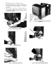


BLOWER WHEEL
PARTITION-
SLOTS
SPRING METAL
CLIP
PARTITION
SLOTS
Fig. 22 — Removing Blower Wheei
SPRING METAL CLIP
Fig. 23 — Removing Outdoor Propeiler Fan
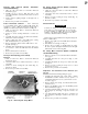
Fan Motor Removal (See Fig. 24)
1. Remove chassis from casing. See Chassis Removal in
structions, page 8.
2. Remove air handling system. See Air Handling System
Removal instructions, page 9.
SCREW
SCREW
PARTITION
SCREW
Fig. 24 - Removing Fan Motor
3. Remove indoor blower wheel and outdoor fan. See
Indoor Blower Wheel Removal and Outdoor Propeller
Fan Removal instructions, page 10.
4. Remove control box. See Control Box Removal instruc
tions, page 5.
5. Carefully disconnect fan motor wiring.
6. Remove 3 screws securing motor to partition. See
Fig. 24.
7. Reverse above procedure for reassembly.
Compressor Removal (See Fig. 15)
NOTE: Before removing compressor, refer to Service sec
tion, page 1, and Carrier Standard Service Techniques
Manual, Chapters 1 and 2.
1. Reclaim all refrigerant from system using a Carrier
Totalclaim® or Carrier Totalsave recovery system, or a
comparable refrigerant recovery system.
2. Remove chassis from casing. See Chassis Removal in
structions, page 8.
3. Remove compressor terminal cover. (See Fig. 15.)
4. Disconnect wires from compressor and external
overload protector terminals Label wires to aid in
reassembly.
NOTE: Some models may have compressors with inter
nal overload protectors.
5. Replace external overload protectors, if needed.
6. Disconnect piping. Refer to Compressor Replacement
section, page 2, being careful to observe all
CAUTIONS.
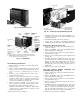
Strainer Removal and Replacement
NOTE: Two strainers are installed in the interconnecting
tubing: one is between the condenser and capillary tube,
and one is between the evaporator and capillary tube. (For
typical location, see Fig 21.)
1. Remove chassis from casing. See Chassis Removal in
structions, page 8.
2. Reclaim all refrigerant from system using a Carrier
Totalclaim or Carrier Totalsave recovery system, or a
comparable system. Refer to Service section, page 1.
3. Cut tubing 1 in. from capillary tube insertion point.
4 Use a thin piece of wire to remove strainer from tubing.
5. Insert new strainer into tubing Reassemble tubing with
field-supplied copper coupling.
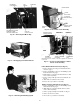
Electric Heater Assembly Removal
1. Remove chassis from casing. See Chassis Removal in
structions, page 8.
2. Remove plastic access cover on top of partition. (See
Fig. 25.)
3. Remove heater assembly (Fig. 26) by lifting straight up,
taking care not to cause fin damage to top of evaporator
coil when heater assembly mounting bracket is lifted off
coil.
4. Remove 2 wires from heater assembly (Fig. 25). Mark
wires to aid in reassembly
5. Repair or replace limit switches (Fig. 26) as needed.
6. Reverse above procedure for reassembly.
11