
User guide


DISASSEMBLY INFORMATION
A WARNING
Before working on any air conditioner, be sure to first
disconnect all electric power to unit to avoid the pos
sibility of electrical shock and personal injury.
_________
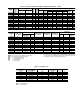
Models 73X,Y Room Air Conditioners have the follow
ing characteristics;
UNIT
FUNCTION
CASING
73XC Cooling Only
305
73XH
Heat/Cool
305
73YC Cooling Only
405
All units have a slide-out chassis. Units can be serviced
without removing casing.
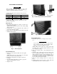
Filter Removal
1.
3.
4.
Place index fingers inside the openings on either side of
the filter frame. See Fig. 1.
Apply pressure inward toward the center, while pulling
filter down and out.
Vacuum filter, or wash in lukewarm water. Shake off
excess water and dry thoroughly.
Replace filter by sliding filter upward behind front grille
until filter snaps in place.
Fig. 1 — Removing Filter
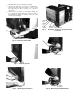
Front Grille Removal
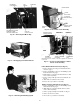
1. Remove 2 screws located on either side of front grille.
See Fig. 2.
NOTE; Facing the front of unit, grille screw on the right-
hand side serves as a unit security screw.
2. Pull grille out and upward, removing it from chassis.
See Fig. 3.
3. To replace grille, place grille top on unit top edge and
firmly press grille back into position.
4. Replace screws.
SCREW (HIDDEN) SCREW (SECURITY)
Fig. 2 - Removing 2 Screws from Front Grille
Fig. 3 - Removing Front Grille
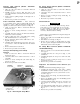
Control Box Removal
1. Slide chassis part way out of casing to access control
box.
A CAUTION
Use care when sliding chassis out of unit so that it
does not fall from casing. Personal injury and/or
damage to unit and surroundings can result.
2.
3.
5.
6.
NOTE; Sliding chassis partly out of casing ensures that
the wiring does not become pinched when the control
box is replaced. See Fig. 4.
Remove front grille. Refer to Front Grille Removal on
this page.
Carefully remove thermostat and mode switch control
knobs by pulling them straight out and off. See Fig. 5.
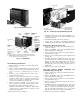
Grasp escutcheon located in lower right-hand corner of
unit and apply pressure on both sides towards the cen
ter. See Fig. 6. Carefully disengage ¿scutcheon plastic
tabs from sheet metal slots and remdve.
Remove 2 screws securing control box to chassis. See
Fig. 7.
Disengage plastic clip, then ybmove sensing bulb with
attached bulb heater from coil face. See Fig. 7.