
User guide


Thermostat Bulb Heater Removal — Use care
not to damage sensing bulb or capillary of thermostat when
handling bulb heater. See Fig. 7.
1. Slide out control box. Refer to Control Box Removal
instructions, page 5.
2. Carefully disconnect bulb heater wires from terminals
Inside control box. Label wires to aid in reassembly.
3. Remove plastic clip used to hold thermostat sensing bulb,
bulb heater, and braided sleeve to coil. (See Fig. 7.)
4. Carefully remove metal clip which connects bulb heater
to sensing bulb.
5. Carefully remove bulb heater wires from braided sleeve
(Fig. 7).
6. Reverse above procedure for reassembly.
Mode Switch Control Removal (See Fig. 9 and
10)
1. Slide out control box. Refer to Control Box Removal
instructions, page 5.
2. Remove 2 screws holding mode switch control to con
trol box. See Fig. 11.
3. Carefully disconnect wires from mode switch control.
Label wires to aid in reassembly.
4. Reverse above procedure for reassembly.
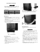
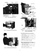
AIR SWEEP MOTOR
(MODELS
73YCA213P, 243P ONLY)
CAPACITOR
STRAP
THERMOSTAT
\
MODE
SELECT
SWITCH
TIMER ASSEMBLY
(MODELS
73YCA213P, 243P
ONLY)
INDICATOR LIGHT WIRES
(MODELS 73YCA213P AND
243P ONLY)
Fig. 9 — Control Box Components
Timer Assembly Removal (Models 73YCA213P
and 73YCA243P Only)
1. Slide out control box. Refer to Control Box Removal
instructions, page 5.
2. Carefully disconnect wires from timer assembly
(Fig. 9). Label wires to aid in reassembly
3. Remove 2 screws securing timer to control box and re
move timer from rear of control box.
4. Reverse procedure for reassembly.
Capacitor Removal
1. Discharge capacitor before removing.
2. Slide out control box. Refer to Control Box Removal
instructions, page 5.
3. Remove screw fastening capacitor strap to control box
and remove strap. (See Fig. 9, 10 and 12.)
4. Carefully disconnect wires from capacitor terminals.
Label wires to aid in reassembly.
5. Reverse above procedure for reassembly.
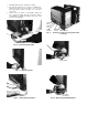
MODE SELECT SWITCH
CAPACITOR Í \
Fig. 10 - Components Layout
THERMOSTAT
SCREWS
SCREWS TO
REMOVE MODE
SELECT SWITCH
BRAIDED SLEEVE
(PROTECTS
SENSOR
BULB AND BULB
HEATER)
Fig. 11 — Removing Thermostat and Bulb Heater
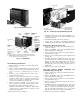
CAPACITOR
STRAP
SCREW
Fig. 12 — Removing Capacitor Strap Screw