
User guide


P
Indicator Light Removal (Models 73YCA213P
and 73YCA243P Only)
1
2.
Slide out control box. Refer to Control Box Removal
instructions, page 5.
Carefully disconnect indicator light wires (Fig. 9 and
13) from termination connections. Label wires to aid in
reassembly.
3. Remove light by pulling straight out through front of
control box.
4. Reverse above procedure for reassembly.
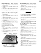
Indoor Thermostat Removal — indoor thermostat
is a vapor-filled device with an attached bulb heater. Be
careful not to bend or kink the thermostat-sensing bulb or
capillary. See thermostat location in control box in Fig. 10.
1. Slide out control box. Refer to Control Box Removal
instructions, page 5.
2. Remove 2 screws securing thermostat to control. See
Fig. 11.
3. Carefully disconnect wires from thermostat terminals.
Label wires to aid in reassembly.
4. Remove plastic clip used to hold bulb heater, sensing
bulb, and braided sleeve to coil. (See Fig. 7.)
5. Remove metal clip which connects bulb heater to sens
ing bulb. (See Fig. 7.)
6. Carefully slide sensing bulb from protective sleeve. It is
not necessary to remove the bulb heater from the braided
sleeve.
7. Remove thermostat from control box.
8. Reverse above procedure for reassembly.
Fan Cycle Switch (Energy Saver Switch)
Removal
1. Slide out control box. Refer to Control Box Removal
instructions, page 5.
2. Disconnect wires from switch. Label wires to aid in
reassembly.
3. Remove 2 screws securing fan cycle switch (Fig. 13)
and remove switch.
4. Reverse above procedure for reassembly.
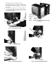
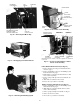
INDICATOR LIGHT
(MODELS 73YCA213P
AND 243P ONLY)
SCREWS FOR
AIR SWEEP MOTOR
AIR SWEEP
SWITCH (MODELS
73YCA213P AND
243P ONLY)
Air Sweep Switch Removal (Models 73YCA213P
and 73YCA243P Only)
1. Slide out control box. Refer to Control Box Removal
instructions, page 5.
2. Disconnect wires from switch. Label wires to aid in
reassembly.
3. Remove 2 screws securing air sweep switch (Fig. 13)
and remove switch.
4. Reverse above procedure for reassembly.
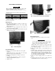
Chassis Removal
A CAUTION
Coil fins are sharp. Use care when removing chassis
from casing to avoid personal injury. Do not use plas
tic parts for lifting or pulling. They are not structural
members of the chassis. Lift using basepan only. Chas
sis is heavy. Obtain assistance for lifting.
Chassis can be serviced without removing unit casing from
window or wall location.
1. Remove front grille. See Front Grille Removal instruc
tions, page 5.
2. Slide chassis out of casing. See Fig. 14.
3. Reverse above procedure to reinstall chassis in casing.
Be sure to replace and tighten left-hand screw and right-
hand security screw on the front grille.
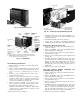
Air Sweep Motor Removal (Models 73YCA213P
and 73YCA243P Only)
1. Remove control box. See Control Box Removal instruc
tions, page 5.
2. Carefully disconnect air sweep motor (Fig. 9) wire
terminations.
3. Carefully pull plastic air sweep motor cam from shaft.
See Fig. 13.
4. Remove 2 screws securing air sweep motor to control
box and remove motor.
5. Reverse above procedure for reassembly.
Evaporator and Condenser Coils Removal (See
Fig. 15)
NOTE; Coils and interconnecting tubing are copper.
1. Reclaim all refrigerant from system using a Carrier
Totalclaim® or Carrier Totalsave recovery system, or a
comparable refrigerant recovery system. Refer to Serv
ice section, page 1.
2. Remove chassis from casing. See Chassis Removal in
structions, above.
3. Remove air handling system. See Air Handling System
Removal instructions, page 9.
4. Cut interconnecting tubing and remove evaporator coil
from basepan by removing 2 evaporator screws. See
Fig. 15.
5. Cut interconnecting tubing and remove condenser coil
from basepan by removing 2 condenser coil screws. See
Fig. 15.
6. Reverse above procedure for reassembly.
Fig. 13 — Removing Air Sweep Motor