
User guide
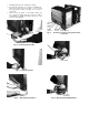


TOP GUSSET
SCREW SECURING
EVAP SCROLL TO
EVAP TUBE SHEET
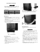
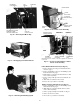
Fig. 14 — Removing Chassis
COMPRESSOR
TERMINAL
COVER
EVAPORATOR
COIL
EVAPORATOR
SCREW
{1 OF 2)
BASEPAN
CONDENSER
EVAPORATOR-" POWER PARTITION ORIFICE SCREW
SCREW (1 OF 2) CORD SCREWS (2) (1 OF 4)
NOTES:
1 Second condenser coil screw is iocated on the back of unit.
2. Third and fourth condenser orifice screws are iocated in same
area on opposite end of condenser orifice
Fig. 15 — Unit Chassis
Air Handling System Removal
1. Remove chassis from casing. See Chassis Removai in
structions, page 8.
2. Remove 2 screws securing partition to basepan as shown
in Fig. 15, and one screw on left side (Fig. 16), and one
screw on rear side of partition (Fig. 17), in area of
motor.
3. Remove 2 screws securing evaporator scroll to evapo
rator tube sheet. See Fig. 16.
4. Remove 4 screws (2 on right side and 2 on left side)
securing condenser orifice to condenser coil tube sheet.
See Fig. 15 for location of right-side screws; left-side
(2) screws are in similar location on left side.
5. Remove compressor terminal cover. Disconnect wires
from compressor and external overload protector termi
nals. Label wires to aid in reassembly. See Fig. 15.
NOTE: Not all models have compressors with external
overload protectors; certain models use compressors with
internal overload protectors
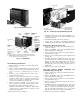
6. Remove fan motor clip. See Fig. 17.
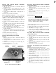
LEFT SIDE
PARTITION SCREW'
SCREW SECURING
EVAP SCROLL TO
EVAP TUBE SHEET
Fig. 16 — Preparing to Lift Air Handling System
7. Carefully disengage one of the vertical air deflectors, al
lowing access to assist in removing air handling system
assembly. See Fig. 18.
8. Carefully lift assembly from chassis. See Fig. 19.
9. Reverse above procedure for reassembly, ensuring air
handling system is positioned correctly. Tighten all screws.
Exhaust Door Removal (See Fig. 20)
1. Remove chassis from casing. See Chassis Removal in
structions on page 8.
2. Remove air handling system. See Air Handling System
Removal Instructions, on this page.
3. Remove control box from chassis. See Control Box Re
moval instructions, page 5.
4. Remove 3 screws securing partition to indoor plastic scroll.
(See Fig. 21.)
5. Carefully separate sheet metal partition slots from scroll
tabs on both sides by spreading sheet metal sides apart.
Remove scroll from sheet metal partition. (See Fig. 22.)
Exhaust door and cable assembly from door to rotary
knob (Fig. 20) are now exposed for required repairs or
adjustments.
6. Reverse above procedure for reassembly.
Vent Door Removal (Models 73YCA213P and
73YCA243P Only) (See Fig. 20)
1. Remove chassis from casing. See Chassis Removal in
structions, page 8.
2. Remove air handling system. See Air Handling System
Removal instructions, on this page.
3. Remove control box from chassis. See Control Box Re
moval instructions, page 5.
4. Remove 3 screws securing center partition to indoor plas
tic scroll. See Fig. 21.
5. Carefully separate sheet metal partition slots from scroll
tabs on both sides by spreading sheet metal sides apart.
Remove scroll from sheet metal partition. See Fig. 22.
Vent door and cable assembly from door to rotary knob
(Fig. 20) are now exposed for repairs or adjustments.
6. Reverse above procedure for reassembly.