
Operating instructions


102
• boards for faulty channels
• faulty transducer
• economizer EXV operation
Slide Valve Control Unverifiable
Alarm 105 — Circuit A (P.87)
Alarm 106 — Circuit B (P.88)
Alarm 107 — Circuit C (P.89)
Criteria for Trip — The criteria are tested when the compres-
sor is operating and the active cooling set point is greater than
32° F (0° C). This alarm will be tripped if the circuit is operat-
ing at 100% of capacity and the measured current is less than
1.1 times the current at fully unloaded 30% for more than one
minute.
Action to be Taken — The affected compressor will continue to
run.
Reset Method — Manual.
Possible Causes — If this condition is encountered, check the
following items:
• faulty unloader solenoid valves
• faulty unloader solenoid coils
• wiring of the unloader solenoid valves
• CPM board for faulty channels
• current transformer reading for accuracy
Alarm 108 — Cooler Flow Switch Setpoint Configuration
Failure (P.90)
NOTE: Alarm 108 is not used or supported. If this condition is
encountered, confirm machine configuration.
Alarm 109 — Cooler Flow Switch Failure (P.91)
Criteria for Trip — The criteria are tested when the unit is on
or off. This alarm will be tripped when the unit is on if:
• The flow switch fails to close after the Off/On delay.
• If the master/slave control is active, the unit is the lag chiller
and if the cooler flow switch fails to close within one minute
after the cooler pump was restarted. The alarm is ignored if
the lag cooler pump is stopped as a result of master/slave
control.
• The flow switch is opened during normal operation.
The alarm will be tripped when the unit is off if:
• The cooler pump control is enabled (Cooler Pumps
Sequence, PUMP=0)
and the cooler flow switch is checked
when the pump is enabled (Flow Checked if C Pump Off,
P. L O C ) and the cooler flow switch is closed after the cooler
pump is commended OFF for more than 2 minutes.
• The flow switch fails to close after the Off/On delay after
the cooler pump has been turned on to protect the cooler
from freezing (Cooler Pumps Sequence, PUMP=0).
Action to be Taken — For criteria for trip A1 and A2, the com-
pressors will not be started.
For criteria for trip A3, all compressors will be stopped without
going through pumpdown. Cooler pump will be stopped with
no delay.
For criteria for trip B1, the unit will not start.
Reset Method — Manual if at least one compressor is operat-
ing. Automatic if no compressors are operating.
Possible Causes — If this condition is encountered, check the
following items:
• a faulty flow switch
• flow switch wiring
• Main Base Board for a faulty channel
• Minutes off time set to 0 (DELY, unit off to on delay)
Alarm 127 —
Water Exchanger Temperature Sensors
Swapped (P.97)
Criteria for Trip — The alarm criterion is checked when the
chiller is ON and one or more compressors is running. This
alarm will be tripped if the entering water temperature is less
than the leaving water temperature for more than 1 minute.
Action to be Taken — The chiller is shut down immediately.
Reset Method — Manual.
Possible Causes — If this condition is encountered, check the
following items:
• Check LWT and EWT wiring at main base board (connec-
tor J6, channels 1,2).
• Check for a faulty entering or leaving water temperature
sensor.
• Check cooler nozzles for proper water temperature sensor
locations.
Alarm 110 — Service Maintenance Alert (Sr.nn)
Criteria for Trip — This alert is tested whether the unit is ON
or OFF and when the Servicing Alert decisions listed under
Time Clock
MCFG have been enabled. The alarm will be
generated if the one of the following configuration errors is
detected by the control. The “nn” refers to the error code listed
in Table 62.
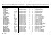
Table 62 — Service Maintenance Alert Codes
Action to be Taken — None.
Reset Method — Manual, after the service has been completed.
Possible Causes — If the Sr-01, 02, or 03 conditions are
encountered, check the following items:
• refrigerant charge
• sensor wiring to the Main Base Board
• sensor for accuracy
Compressor Motor Temperature Too High
Alarm 111-01 — Circuit A (A1.01)
Alarm 112-01 — Circuit B (B1.01)
Alarm 113-01 — Circuit C (C1.01)
Criteria for Trip — The alarm criteria are checked when the
compressor is ON. This alarm will be generated if:
• The temperature is greater than 245 F (118 C) and it has
been greater than 212 F (100 C) for 10 consecutive seconds.
• The compressor temperature is greater than 232 F (111 C)
for 90 seconds (but less than 250 F [120 C]).
Action to be Taken — The circuit shuts down immediately.
Reset Method — Manual
Possible Causes — If this condition is encountered, check the
following items:
• faulty wiring and loose plugs
• faulty CPM board
Compressor Motor Temperature Out of Range
Alarm 111-02 — Circuit A (A1.02)
Alarm 112-02 — Circuit B (B1.02)
Alarm 113-02 — Circuit C (C1.02)
Criteria for Trip — The alarm criterion is checked when the
compressor is ON. This alarm will be generated if: the temper-
ature is greater than 245 F (118 C) and it has NOT been greater
than 212 F (100 C) for 10 consecutive seconds.
CODE DESCRIPTION
Sr.01 Circuit A Loss of Refrigerant Charge
Sr.02 Circuit B Loss of Refrigerant Charge
Sr.03 Circuit C Loss of Refrigerant Charge
Sr.04 Water Loop Size Warning
Sr.05 Air Exchanger Cleanliness Warning
Sr.06 Cooler Pump 1 Servicing Required
Sr.07 Cooler Pump 2 Servicing Required
Sr.08 Condenser Pump 1 Servicing Required
Sr.09 Condenser Pump 2 Servicing Required
Sr.10 Water Filter Servicing Required
Sr.11 Compressor A Oil Filter Servicing Required
Sr.12 Compressor B Oil Filter Servicing Required
Sr.13 Compressor C Oil Filter Servicing Required