
Operating instructions

3
GENERAL
This publication contains Controls, Operation, Start-Up,
Service and Troubleshooting information for the 30XA080-
500 air-cooled liquid chillers with electronic controls. The
30XA chillers are equipped with ComfortLink™ controls and
electronic expansion valves. The AquaForce
®
30XA chillers
offer two different user interface devices, the Touch Pilot™
display and the Navigator ™ display.
Conventions Used in This Manual — The follow-
ing conventions for discussing configuration points for the
Navigator module and Touch Pilot display will be used in this
manual.
Point names for the Touch Pilot display will be shown in
bold. See Appendix A for a complete list of point names. Item
names for the Navigator module will be shown in bold italics.
See Appendix B for the complete path name preceeding the
item name. The point and item names in Appendices A and B
will be listed in alphabetical order and the path name for each
will be written with the mode name first, then any sub-modes,
each separated by an arrow symbol (.
This path name will show the user how to navigate through the
Navigator module or the Touch Pilot display to reach the desired
configuration. The user would scroll through the modes and
sub-modes using the and keys on the Navigator display.
For the Touch Pilot display, the user would simply touch the menu
item on the screen. The arrow symbol in the path name represents
pressing to move into the next level of the menu struc-
ture for the Navigator module, or touching the menu item on the
screen for the Touch Pilot display.
When a value is included as part of the point name, it will be
shown after the point name after an equals sign. If the value
represents a configuration setting, an explanation will be
shown in parentheses after the value. The Touch Pilot name
will be shown first with the Navigator name following. As an
example,
(Staged Loading Sequence = 1, LLCS = Circuit A leads).
Press the and keys simultaneously on
the Navigator module to display an expanded text description of
the point name or value. The expanded description is shown in the
Navigator display tables (Appendix B) but will not be shown with
the path names in text. The Touch Pilot display will show an
expanded description of the point name. To view the expanded
point name for the Touch Pilot display go to Appendix A.
The Touch Pilot display configures the unit via the CCN
(Carrier Comfort Network
®
) Tables, which are located in Ap-
pendix C of this manual.
Display Module Usage
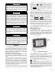
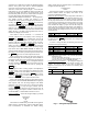
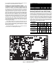
TOUCH PILOT DISPLAY — The Touch Pilot display is the
standard user interface for the AquaForce 30XA chillers with
the ComfortLink control system. The display includes a large
LCD (liquid crystal display) touch screen for display and user
configuration, a Start/Stop button, and an Alarm Indicator LED
(light-emitting diode). See Fig. 1.
The Touch Pilot display can be used to access various
Carrier Comfort Network
®
devices. For operation under these
circumstances, contact your Carrier representative.
Operation of the Touch Pilot display is driven from the
displays on the touch screen. The Touch Pilot display uses the
following screen “buttons” to allow the user to operate the dis-
play and navigate within and between screens.
“BACK” Returns to the next higher screen in the
hierarchy.
“HOME” Displays the Default Group Display screen
for Touch Pilot display. The Default Screen is a user-
configured display of up to 9 points on each of 8 screens. This
allows for quick access to various, frequently viewed points,
without navigating through the Main Menu structure. This but-
ton is available at all menu levels and returns the user to the
first Default Group Display screen.
CAUTION
This unit uses a microprocessor-based electronic control
system. Do not use jumpers or other tools to short out com-
ponents, or to bypass or otherwise depart from recom-
mended procedures. Any short-to-ground of the control
board or accompanying wiring may destroy the electronic
modules or electrical components.
CAUTION
To prevent potential damage to heat exchanger tubes,
always run fluid through heat exchanger when adding or
removing refrigerant charge. Use appropriate antifreeze
solutions in cooler fluid loop to prevent the freezing of heat
exchanger or interconnecting piping when the equipment is
exposed to temperatures below 32 F (0° C). Proof of flow
switch is factory installed on all models. Do NOT remove
power from this chiller during winter shut down periods
without taking precaution to remove all water from heat
exchanger. Failure to properly protect the system from
freezing may constitute abuse and may void warranty.
CAUTION
Compressors require specific rotation. Test condenser
fan(s) first to ensure proper phasing. Swap any two incom-
ing power leads to correct condenser fan rotation before
starting compressors. Operating the unit without testing the
condenser fan(s) for proper phasing could result in equip-
ment damage.
CAUTION
DO NOT re-use compressor oil or any oil that has been
exposed to the atmosphere. Dispose of oil per local codes
and regulations. DO NOT leave refrigerant system open to
air any longer than the actual time required to service the
equipment. Seal circuits being serviced and charge with
dry nitrogen to prevent oil contamination when timely
repairs cannot be completed. Failure to follow these proce-
dures may result in damage to equipment.
ENTER
ESCAPE
ENTER
STA R T- STOP
BUTTON
LCD TOUCH SCREEN
ALARM
INDICATOR
LIGHT
Fig. 1 — Touch Pilot™ Display
Figure-1
612