
Operating instructions

32
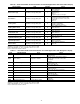
To configure this option with the Touch Pilot display:
To configure this option with the Navigator display:
CIRCUIT/COMPRESSOR LOADING — The control can
be configured to stage the circuit/compressors. The Loading
Sequence Select (Circuit Loading Sequence, LOAD) setting
determines how the control will perform loading. The configu-
ration can be set to Equal or Staged.
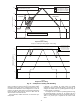
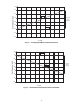
Equal Loading
— With Equal loading, the circuit which starts
first will maintain the minimum stage of capacity with the slide
valve fully unloaded. When additional capacity is required, the
next circuit with the lowest compressor wear factor is started
with its slide valve at minimum position. As additional capaci-
ty is required, the slide valve for a circuit will be adjusted in
approximately 5% increments to match capacity requirements.
The control will alternate between circuits to maintain the same
percentage of capacity on each circuit. See Fig. 21.
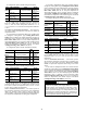
Staged Loading
— If staged loading is selected, the circuit
which starts first will gradually load its slide valve to match
capacity requirements until the circuit is fully loaded. Once the
circuit is fully loaded and additional capacity is required, the
control will start an additional circuit fully unloaded. The con-
trol will gradually unload the circuit which was fully loaded to
match capacity requirements. See Fig. 21.
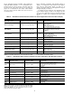
To configure this option with the Touch Pilot™ display:
To configure this option with the Navigator™ display:
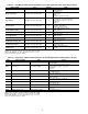
Minimum Load Control — Minimum Load Control
can be a factory-installed option or a field-installed accessory.
If installed, and its operation is desired, the Minimum Load
Control must be enabled. Once enabled, the valve will be oper-
ational only during the first stage of cooling.
To configure this option with the Touch Pilot display:
To configure this option with the Navigator display:
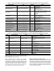
Dual Chiller Control — The dual chiller routine is
available for the control of two units installed in series or paral-
lel supplying chilled fluid on a common loop. One chiller must
be configured as the master chiller, the other as the slave chill-
er. An additional leaving fluid temperature thermistor (Dual
Chiller LWT) must be installed in the common chilled water
piping as described in the Installation Instructions for both the
master and slave chillers. See the Field Wiring section in the
30XA Installation Instructions for Dual Chiller LWT sensor
control wiring.
The control algorithm relies on several parameters that must
be field configured for operation. Both chillers must be on the
same Carrier Comfort Network
®
bus with different addresses.
On both chillers, Master/Slave Select (Master/Slave Select,
MSSL) must be enabled. The water piping arrangement, Chill-
ers in Series (Chiller in Series, SERI), must be configured.
The master chiller must be programmed with the Slave Chiller
Address (Slave Address, SLVA). Additional optional pro-
gramming parameters may be configured to meet application
requirements.
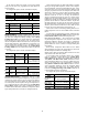
Lead/Lag Balance Select (Lead Lag Select, LLBL) deter-
mines which chiller is the lead machine. The options are Al-
ways Lead, Lag if Fail, and Runtime Select. Under Runtime
Select control, the lead chiller will change based on the time in-
crement selected in the Lead/Lag Balance Delta configuration
(Lead/Lag Balance Data, LLBD). If the run hour difference
between the master and the slave remains less than the Lead/
Lag Balance Delta, the chiller designated as the lead will
remain the lead chiller. The Lead/Lag changeover between the
master and the slave chiller due to hour balance will occur dur-
ing chiller operating odd days, such as day 1, day 3, and day 5
of the month, at 12:00 a.m. If a lead chiller is not designated,
the master chiller will always be designated the lead chiller.
The dual chiller control algorithm has the ability to delay
the start of the lag chiller in two ways. The Lead Pulldown
Time parameter (Lead Pulldown Type, LPUL) is a one-time
time delay initiated after starting the lead chiller, before check-
ing whether to start an additional chiller. This time delay gives
the lead chiller a chance to remove the heat that the chilled
water loop picked up while being inactive during an unoccu-
pied period. The second time delay, Lead/Lag Delay (Lag
Start Timer, LLDY) is a time delay imposed between the last
stage of the lead chiller and the start of the lag chiller. This pre-
vents enabling the lag chiller until the lead/lag delay timer has
expired.
A quicker start of the lag chiller can be accomplished by
configuring the Start if Error Higher parameter (Start if Error
Higher, LL.ER). If the difference between the common leav-
ing water temperature and the set point is greater than the con-
figured value, then the lag chiller will start.
A minimum on time for the lag chiller can be programmed
with the Lag Minimum Running Time configuration (Lag
Minimum Running Time, LAG.M). This parameter causes
the control to run the lag chiller for the programmed minimum
on time. The Lag Unit Pump Select (Lag Unit Pump Control,
LAGP) can be configured such that the pump can be on or off
while the chiller is off. This parameter is only active in Parallel
Chiller Operation.
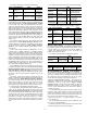
DISPLAY NAME PATH
LINE
NO.
VALUE
Circuit Loading
Sequence
Main Menu
ConfigUSER
1
0 (Automatic Lead-lag)
1 (Circuit A Leads)
2 (Circuit B Leads)
3 (Circuit C Leads)
Default = 0
(Automatic Lead-lag)
ITEM ITEM EXPANSION PATH VALUE
LLCS
Lead/Lag
Circuit Select
Configuration
OPTN
Range: Automatic,
Cir A Leads,
Cir B Leads,
Cir C Leads
Default – Automatic
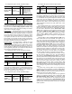
DISPLAY NAME PATH
LINE
NO.
VALUE
Staged Loading
Sequence
Main
Menu
ConfigUSER
4
Default = No
No (Equal)
Yes (Staged)
ITEM ITEM EXPANSION PATH VALUE
LOAD
Loading Sequence
Select
Configuration
OPTN
Default = Equal
Equal
Staged
DISPLAY NAME PATH
LINE
NO.
VALUE
Hot Gas
Bypass Select
Main
Menu
Service
FACTORY
14
Default = No
No (No Minimum
Load Control)
Yes (Minimum Load
Control Installed)
ITEM
ITEM
EXPANSION
PATH VALUE
HGBP
Hot Gas
Bypass Select
Configuration
UNIT
No = No Minimum
Load Control
Yes = Minimum Load
Control Installed