
Operating instructions

37
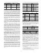
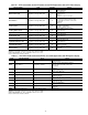
Table 34 — Dual Slave Chiller Control Parameters for Series Applications with Touch Pilot Display
NOTE: If pump control is configured to OFF, then LAG UNIT PUMP
SELECT = 1. If pump control is set to any other value, then LAG
UNIT PUMP SELECT = 0. This configuration must be set consis-
tently for both master and slave chillers.
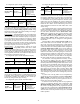
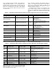
Table 35 — Dual Slave Chiller Control Parameters for Series Applications with Navigator Display
NOTE: If pump control is configured to OFF, then LAG UNIT PUMP
SELECT = 1. If pump control is set to any other value, then LAG
UNIT PUMP SELECT = 0. This configuration must be set consis-
tently for both master and slave chillers.
DUAL CHILLER PUMP CONTROL FOR SERIES
CHILLER APPLICATIONS — Pump control for series chill-
er applications is controlled by the master chiller only. The
control of the slave chiller is directed through commands emit-
ted by the master chiller. The slave chiller has no action in
master/slave operations. The slave chiller only verifies that
CCN communication with the master chiller is present. See the
Dual Chiller Sequence of Operation section on page 68.
Night Time/Low Noise Operation — The Com-
fortLink™ controls have the ability to lower the sound level of
the machine by reducing the number of fans that are running,
provided that the conditions are acceptable. Reducing the num-
ber of running fans also limits the capacity. Three parameters
must be configured for this operation. A start and end time for
the mode of operation is required and an optional capacity limit
set point must also be configured.
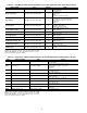
DISPLAY NAME PATH LINE NO. VALUE
Master/Slave Select Main MenuConfigMST_SLV 3
2 (Slave)
Default: 0 (Disable)
Master Control Type Main Menu
ConfigMST_SLV 7
1 (Local Control)
2 (Remote Control)
3 (CCN Control)
Default: 1 (Local Control)
Value: Configure for proper control type.
Slave Address Main Menu
ConfigMST_SLV 11
Must be set to the Slave Chiller’s address.
The master and slave chiller must have
different addresses and be on the same
Bus Number
Default: 2
Lead Lag Select Main Menu
ConfigMST_SLV 12
0 (Master Always Leads)
1 (Lag Once Failed Only)
2 (Lead/Lag Runtime Select)
Default: 0 (Master Always Leads)
Lead/Lag Balance Delta Main Menu
ConfigMST_SLV 16
Range: 40 to 400 hours
Default: 168 hours
Lag Start Timer Main Menu
ConfigMST_SLV 17
Range: 2 to 30 minutes
Default: 10 minutes
Lead Pulldown Time Main Menu
ConfigMST_SLV 18
Range: 0 to 60 minutes
Default: 0 minutes
Start If Error Higher Main Menu
ConfigMST_SLV 19
Range: 3.0 to 18 F (1.7 to 10.0 C)
Default: 4.0 F (2.2 C)
Lag Minimum Running Time Main Menu
ConfigMST_SLV 20
Range: 0 to 150 minutes
Default: 0 minutes
Lag Unit Pump Control Main Menu
ConfigMST_SLV 21
0 (Stop If Unit Stops)
1 (Run If Unit Stops)
Default: 0 (Stop If Unit Stops)
Chiller In Series Main MenuConfigMST_SLV 22
Ye s
Default: No
ITEM ITEM EXPANSION PATH VALUE
MSSL Master/Slave Select ConfigurationRSET
Slave
Default: Disable
SLVA Slave Address ConfigurationRSET
Must be set to the Slave Chiller’s address.
The master and slave chiller must have
different addresses and be on the same
Bus Number
Default: 2
LLBL Master Lead Lag Select Configuration
RSET
Range: Always Lead, Lag if Fail,
Runtime Sel
Default: Always Lead
LLBD Lead/Lag Balance Delta Configuration
RSET
Range: 40 to 400 hours
Default: 168 hours
LLDY Lag Start Delay Configuration
RSET
Range: 2 to 30 minutes
Default: 10 minutes
LL.ER Start If Error Higher Configuration
RSET
Range: 3.0 to 18 F (1.7 to 10.0 C)
Default: 4.0 F (2.2 C)
LAG.M Lag Unit Pump Select Configuration
RSET
Range: Off If U Stp, On If U Stop
Default: Off If U Stp
LPUL Lead Pulldown Time Configuration
RSET
Range: 0 to 60 minutes
Default: 0 minutes
SERI Chillers in Series Configuration
RSET
YES
Default: NO
OPER Operating Control Type Operating ModesSLCT CCN Control